
Electrocautery method and system

a technology of electrocautery and system, applied in the field of system for performing electrocautery surgery, can solve the problems of large force needed to pull tissue out of the way, insufficient heat to explode or rupture tissue cells, and inability to accurately measure the thickness of the tissu

Inactive Publication Date: 2006-03-16
SECURIT E DOC
View PDF12 Cites 15 Cited by
  • Summary
  • Abstract
  • Description
  • Claims
  • Application Information

AI Technical Summary

Benefits of technology

"The invention provides a system and method for performing electrocautery using a non-conductive retractor to protect the patient from injury. The retractor is made of a strong material that can safely retract tissue during surgery. The non-conductive retractor is particularly useful for small incisions and cosmetic or surgery on the breasts, head or neck. The technical effect of the invention is to reduce the risk of injury to patients during electrocautery surgery."

Problems solved by technology

A high current density at the narrow leading edge transfers energy into the tissue as relatively short arcs, thereby causing enough heat to explode or rupture the cells of the tissue at the interface with the narrow leading edge.
In fact, the narrow edge of the typical electrocauteral blade is typically not sharp and typically cannot cut tissue as a result of mechanical action.
Frequently, considerable force is needed to pull tissue out of the way during electrocautery.
This can lead to burning or discoloration of the tissue or skin in contact with the retractor.
This can be particularly undesirable during certain surgeries, such as breast, head or neck surgery, as undo trauma, discoloration or otherwise altering the skin in the breast area can be deleterious to the patient's psychological condition as well as leading to medical complications.

Method used


Image

  • Electrocautery method and system
  • Electrocautery method and system

Examples


Embodiment Construction

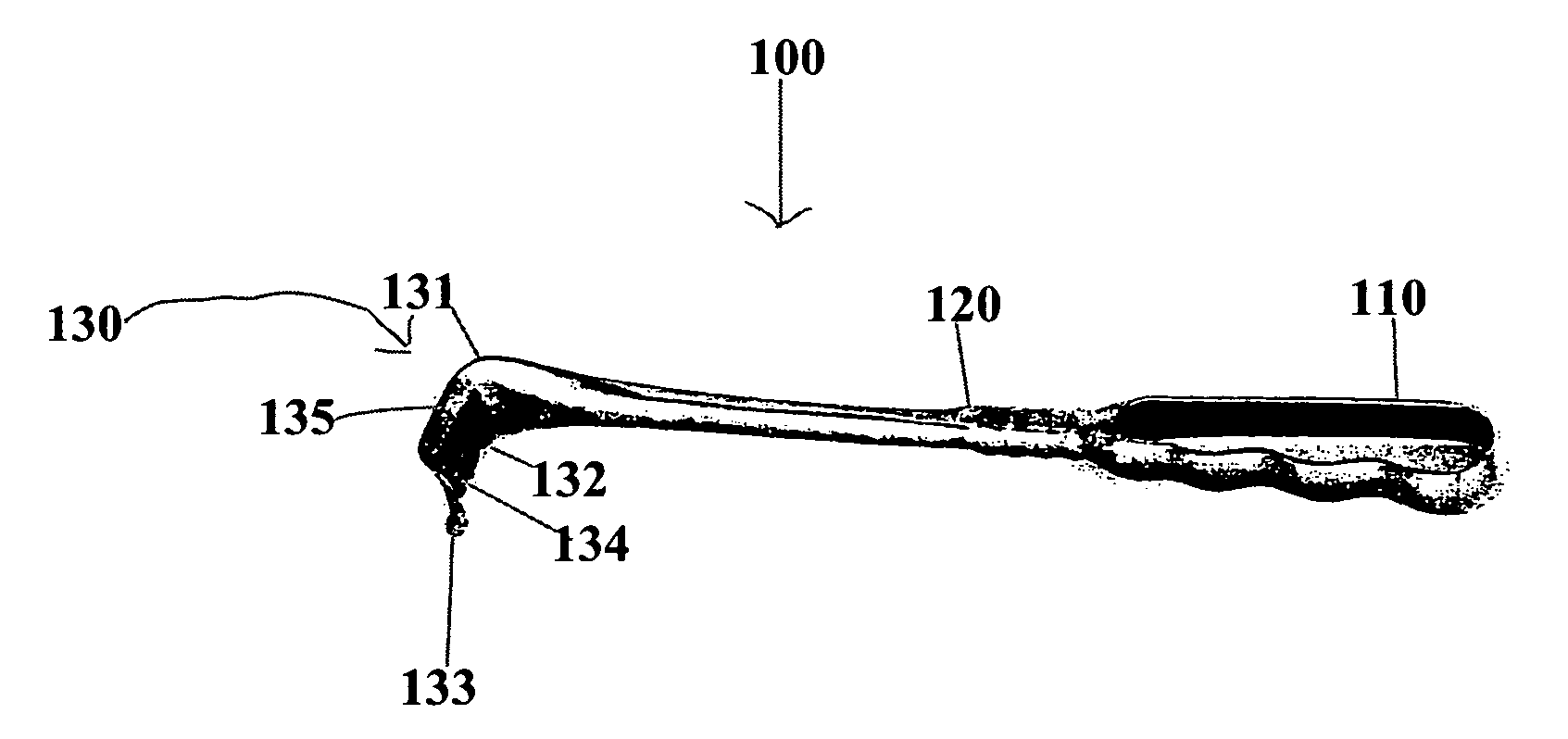
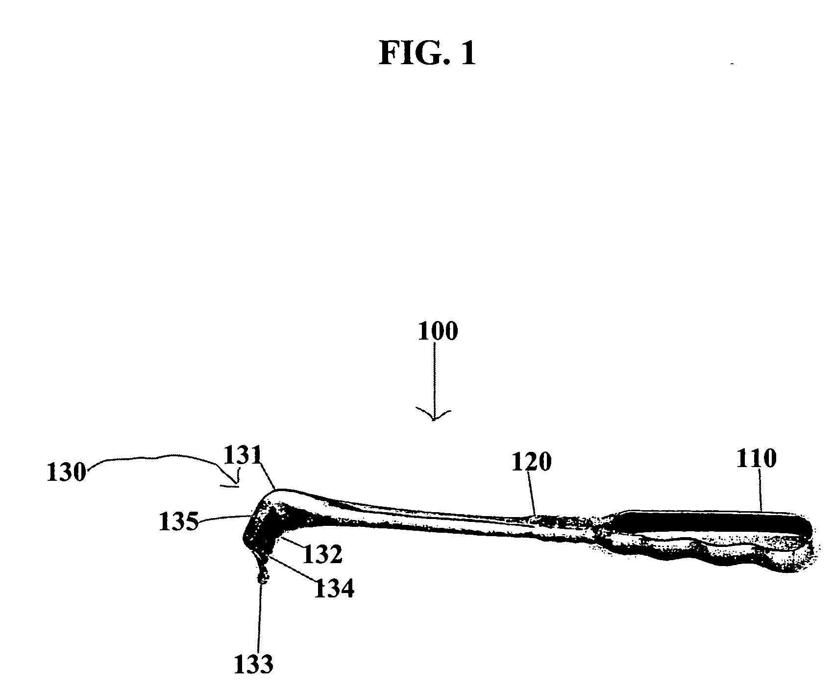
[0015] The invention relates to a system for performing electrocautery that permits more precise use of the electrocauteral blade and helps prevent scarring and discoloration of the skin during electrocautery. Systems in accordance with the invention comprise an electrocauteral apparatus in combination with an electrically non-conductive retractor.

[0016] The electrocautery is performed by the application of relatively high-frequency or radio frequency (RF) current to living tissue. By varying the characteristics of the current, the electrocauteral apparatus can be used to cut tissue, to coagulated bleeding from the tissue or to both cut tissue and promote hemostasis simultaneously. Acceptable frequencies of the electrocauteral device can range from approximately 400 kHz to 750 kHz. The electrical power applied can vary from a few watts for delicate neurosurgical procedures to 300 watts or more for cutting substantial tissues in open surgical procedures. The open circuit voltage pri...


PUM


Abstract

A system and method for performing electrocautery is provided in which the surgeon need not worry about injuring the patient by placing the electrocauteral blade too close to the retractor. This system and method is implemented by forming at least the retracting end of the retractor from an electrically non-conductive material. In one embodiment of the invention, the retractor is formed from the electrically insulating material, such, for example, plastic, especially heat resistant clear plastic. Thermosetting resins, and other polymers particularly those having filters to increase heat resistance are preferred. The electrically non-conductive retractor is used to retract the skin as the electrocauteral blade is used to cut and / or coagulate. Methods in accordance with invention are particularly useful when the initial incision is small, such as in the one to five, preferably two to four inch range. Methods and systems in accordance with the invention are particularly preferred during cosmetic surgery and / or surgery on the breasts, head or neck. Accordingly, it is an object of the invention to provide an improved system and method for performing electrocautery.

Description

CROSS-REFERENCE TO RELATED APPLICATIONS [0001] This application claims the benefit of Provisional Patent Application No. 60 / 488,179, which is incorporated herein by reference.BACKGROUND OF INVENTION [0002] The invention relates to a system for performing electrocauteral surgery (i.e., electrosurgery) that permits more precise use of the electrocauteral blade and helps prevent scarring and discoloration of the skin and other body tissue during electrocautery. [0003] Electrocautery involves the application of relatively high-frequency or radio frequency (RF) current to living tissue. By varying the characteristics of the current, an electrocauteral apparatus can be used to cut tissue, to coagulate bleeding from the tissue (hemostasis) or to both cut tissue and promote hemostasis simultaneously. One example of an electrocauteral device is the Valleylab Force Fx Instant Response Electrosurgical Generator, sold by Valleylab Inc. of Boulder, Colo. [0004] Electrocautery is performed by con...

Claims


Application Information

Patent Timeline
Patent Type & Authority Applications(United States)
IPC IPC(8): A61B18/04A61BA61B17/02A61B18/14
CPCA61B18/1402A61B17/02
Inventor BROUKHIM, MARYAM
Owner SECURIT E DOC
Learn More