
Enhanced polling method for preventing deadlock in a wireless communications system

a wireless communication system and polling mechanism technology, applied in the field of wireless communication, can solve the problems of additional overhead in transmission airtime and system requirements, and the extra effort required to employ this transmission mode, and achieve the effect of preventing deadlock and reducing the number of polls

Active Publication Date: 2006-03-16
INNOVATIVE SONIC
View PDF1 Cites 121 Cited by
  • Summary
  • Abstract
  • Description
  • Claims
  • Application Information

AI Technical Summary

Benefits of technology

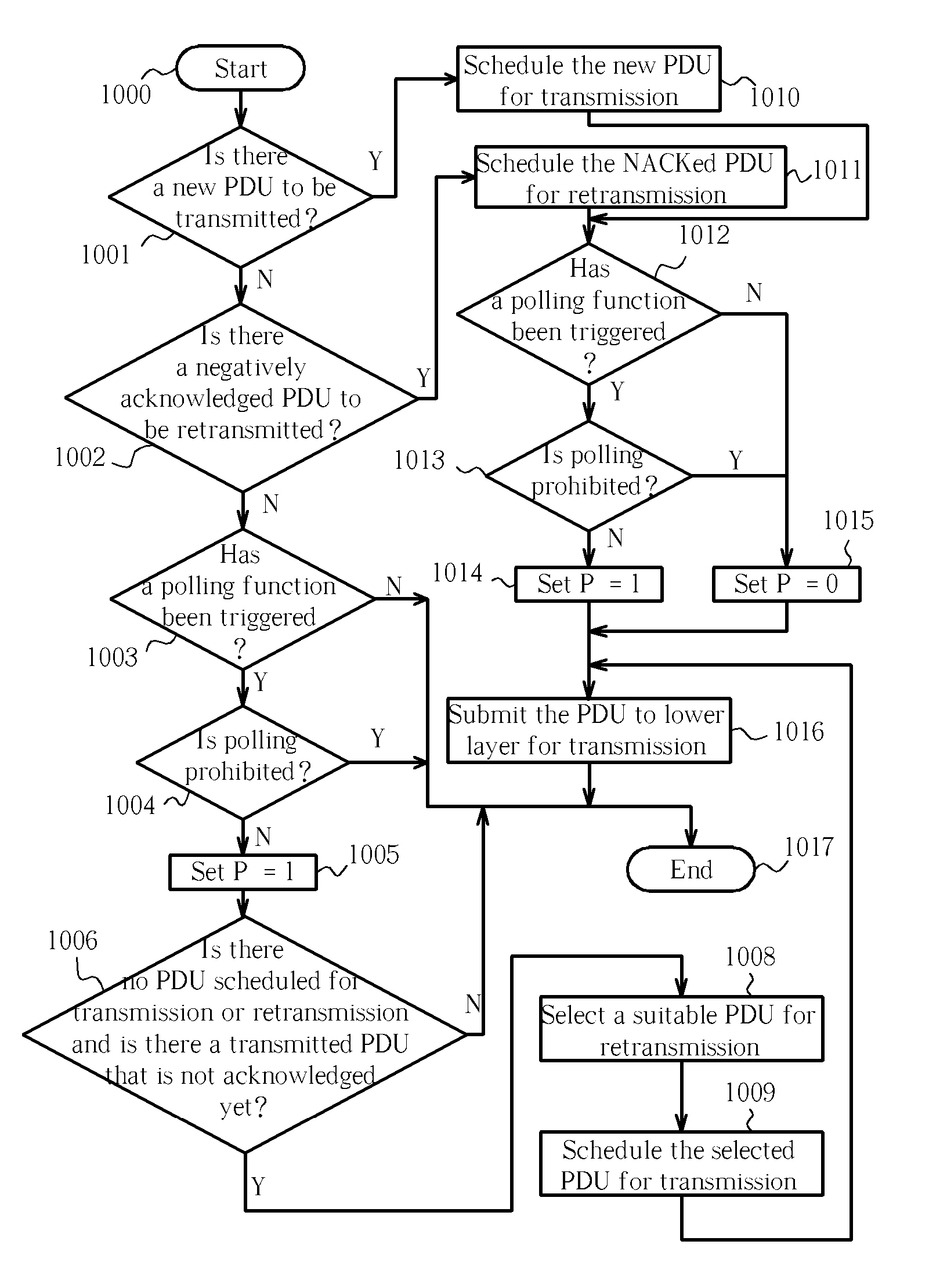
[0058] A method of polling in a wireless communications system includes prohibiting polling within a first predetermined period and triggering a poll function while polling is prohibited. After the first predetermined period has expired the method determines that there are no protocol data units (PDUs) scheduled for transmission or re-transmission and that there is at least a transmitted PDU that is not acknowledged yet, and selects a PDU to schedule for re-transmission to fulfill the triggered poll function. The trigger to trigger a polling function includes a trigger that triggers a poll function when a last PDU in a buffer for first-time transmission is scheduled for transmission, a trigger that triggers a poll function when a last PDU in a buffer for re-transmission is scheduled for re-transmission, a trigger that triggers a poll function when every first predetermined number of PDUs are scheduled for transmission or re-transmission, a trigger that triggers a poll function when every second predetermined number of service data units (SDUs) are scheduled for transmission, and a trigger that triggers a poll function when a predetermined percentage of a transmission window is reached.

Problems solved by technology

The extra effort required to employ this transmission mode carries an additional overhead in terms of transmission airtime and system requirements.
Unfortunately, there are situations allowable in the prior art whereby ‘deadlock’ may arise.

Method used


Image

  • Enhanced polling method for preventing deadlock in a wireless communications system
  • Enhanced polling method for preventing deadlock in a wireless communications system
  • Enhanced polling method for preventing deadlock in a wireless communications system

Examples


Embodiment Construction

[0069] In order to overcome the prior art problems described above, a preferred embodiment method of the present invention is described by example below.

[0070] Assuming the configuration of the transmitting and the receiving stations is the same as that given in the prior art examples illustrated by FIGS. 5 and 6 above, i.e. the transmitter is configured by upper layers to enable the following five poll triggers:

[0071] (1) “Last PDU in buffer (for first time transmission)”,

[0072] (2) “Last PDU in Retransmission buffer”,

[0073] (3) “Poll timer” (with Timer_Poll=200 ms),

[0074] (4) “Every Poll_PDU PDU” (with Poll_PDU=4), and

[0075] (5) “Every Poll_SDU SDU” (with Poll_SDU=4).

[0076] And also assuming that: ‘window based’ triggers and ‘timer based’ triggers are disabled, the poll prohibit function is configured with Timer_Poll_Prohibit=250 ms, one SDU is requested for transmission by an upper layer and an RLC transmission confirmation is requested by the upper layer when transmission...


PUM


Abstract

A method of polling in a wireless communications system includes prohibiting polling within a first predetermined period and triggering a poll function while polling is prohibited. After the first predetermined period has expired the method determines that there are no protocol data units (PDUs) scheduled for transmission or re-transmission and that there is at least a transmitted PDU that is not acknowledged yet, and selects a PDU to schedule for re-transmission to fulfill the poll function.

Description

CROSS REFERENCE TO RELATED APPLICATIONS [0001] This application claims the benefit of U.S. Provisional Application No. 60 / 522,324, filed Sep. 15, 2004, entitled “Enhanced Polling Mechanism and Device in a Wireless Communications System” and included herein by reference.BACKGROUND OF THE INVENTION [0002] 1. Field of the Invention [0003] The present invention relates to wireless communications. More particularly, the present invention relates to an enhanced polling mechanism and device in a 3GPP wireless communications system. [0004] 2. Description of the Prior Art [0005] The surge in public demand for wireless communication devices has placed pressure upon industry to develop increasingly sophisticated communications standards. The 3rd Generation Partnership Project (3GPP™) is an example of such a new communications protocol. The 3rd Generation Partnership Project (3GPP) specification, 25.322 V6.1.0 (2004-06) Radio Link Control (RLC) protocol specification (referred to hereinafter as...

Claims


Application Information

Patent Timeline
IPC IPC(8): H04L12/403H04L12/42H04L1/16H04L1/18H04W28/04H04W74/06
CPCH04L1/1685H04W74/06H04W28/04H04L1/1883H04W72/12H04L1/16
Inventor JIANG, SAM SHIAW-SHIANG
Owner INNOVATIVE SONIC
Learn More