
Reverse rotation preventing electronic cam curve generating method based on electronic cam type rotary cutter control and control device therefor

a technology of electronic cam and control device, which is applied in the direction of electric programme control, program control, instruments, etc., can solve problems such as mechanical trouble, and achieve the effect of preventing a reverse rotation and simple and rapid calculation

Inactive Publication Date: 2006-03-16
YASKAWA DENKI KK
View PDF5 Cites 5 Cited by
  • Summary
  • Abstract
  • Description
  • Claims
  • Application Information

AI Technical Summary

Benefits of technology

[0009] According to the reverse rotation preventing electronic cam curve generating method of an electronic cam type rotary cutter control, the cutting length Ljag in which the rotary cutter is reversely rotated is previously obtained by a calculation, and such an electronic cam curve as to avoid the reverse rotation is created to carry out a control when the cutting length Lset of a workpiece is greater than the cutting length Ljag Therefore, the reverse rotation of the cutter can be automatically prevented perfectly.
[0011] According to the reverse rotation preventing electronic cam curve generating method of an electronic cam type rotary cutter control, it is possible to accurately calculate a critical cutting length.
[0013] According to the reverse rotation preventing electronic cam curve generating method of an electronic cam type rotary cutter control, it is possible to freely generate an optional pattern without changing an algorithm including an electronic cam curve pattern to avoid a reverse rotation by simply changing the six parameters in the above equations.
[0016] According to the reverse rotation preventing electronic cam curve generating method of an electronic cam type rotary cutter control, it is possible to create, as an effective command, such an electronic cam curve pattern as to prevent the reverse rotation of a cutter by using data on an actual cutter.
[0018] According to the reverse rotation preventing electronic cam curve generating method of an electronic cam type rotary cutter control, one cutting cycle period Tc to be the control unit of a controller is subdivided (for example, divided into five parts of 1 to 5 sections), and both the speed function and the position function are calculated for each of the sections by using a trigonometric function approximate equation to wholly carry out a synthesis, thereby generating an electronic cam curve pattern. By a simple and rapid calculation in which an algorithm does not need to be changed, therefore, it is possible to draw a smooth electronic cam curve pattern without generating any shock due to a change in an acceleration including an electronic cam curve pattern for preventing a reverse rotation.

Problems solved by technology

Therefore, there is a problem in that a mechanical trouble is made, that is, “an object to be cut crashes against a blade rotated reversely”.

Method used


Image

  • Reverse rotation preventing electronic cam curve generating method based on electronic cam type rotary cutter control and control device therefor
  • Reverse rotation preventing electronic cam curve generating method based on electronic cam type rotary cutter control and control device therefor
  • Reverse rotation preventing electronic cam curve generating method based on electronic cam type rotary cutter control and control device therefor

Examples


Embodiment Construction

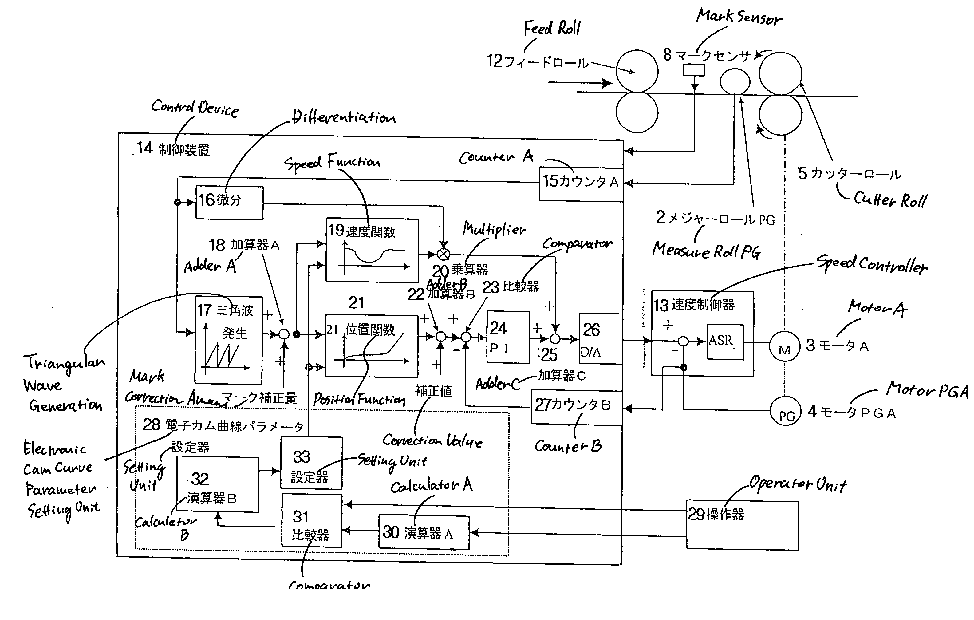
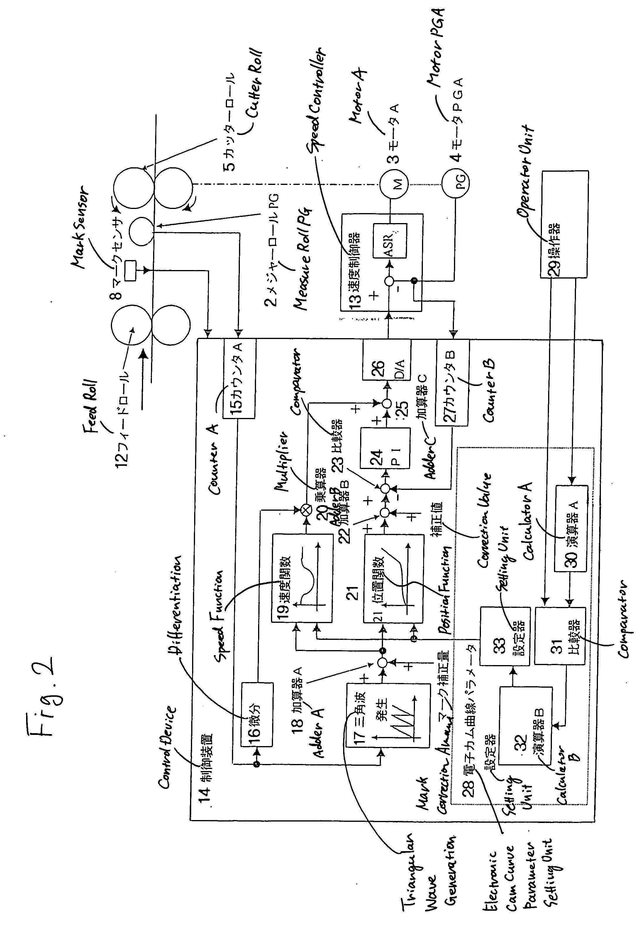
[0032] Next, an embodiment of the invention will be described with reference to the drawings.

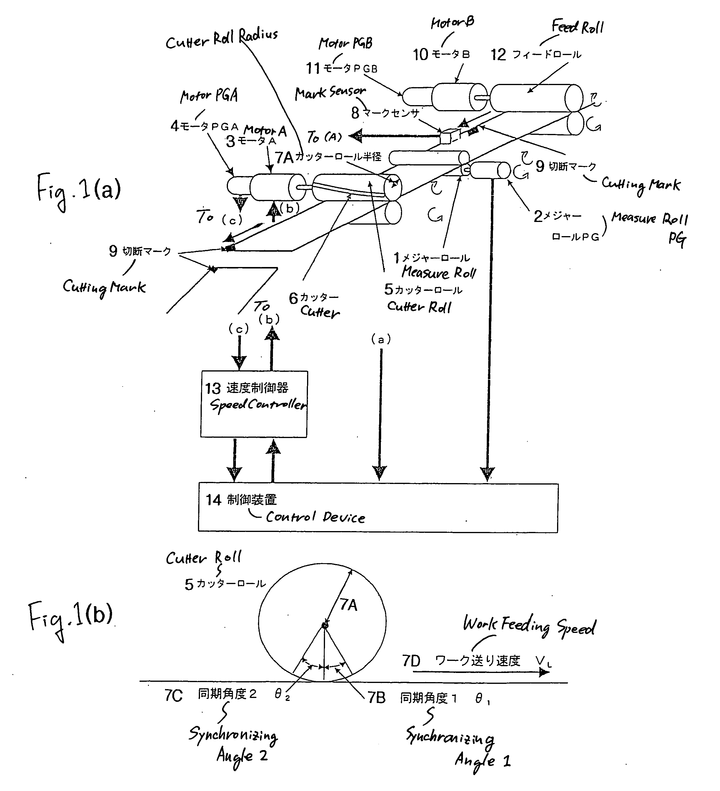
[0033]FIG. 1 is a view showing the structure of a rotary cutter machine to which a reverse rotation preventing electronic cam curve generating method according to an embodiment of the invention is applied.

[0034] In FIG. 1, FIG. 1(a) is a view showing the structure of a rotary cutter machine and FIG. 1(b) is a view for explaining a cutter roll. Referring to the machine in FIG. 1(a), a machine apparatus constituted by a measure roll 1, a cutter roll 5 and a feed roll 12 is provided with a measure roll PG2, a motor A3, a motor PG4, a mark sensor 8, a motor B10, a motor PG11, a speed controller 13, and a control device 14.

[0035]FIG. 1(b) is a sectional view showing the cutter roll 5, illustrating a cutter roll radius r7A, a workpiece feeding speed VL7D, and a synchronizing angle 1θ17B and a synchronizing angle 2θ27C in a synchronizing section (a cutting section).

[0036] In FIG. 2, the control...


PUM

PropertyMeasurementUnit
Lengthaaaaaaaaaa
Speedaaaaaaaaaa

Abstract

It is an object of the invention to provide a reverse rotation preventing electronic cam curve generating method of an electronic cam type rotary cutter control which serves to prevent the reverse rotation of a cutter. According to the invention, there is provided an electronic cam curve parameter setting unit 28 for previously calculating a critical cutting length Ljag from which an electronic cam curve passing through a point having an acceleration of 0 and a speed of 0 is obtained by setting a rotor diameter r of a rotary cutter 5, the number of blades M disposed at regular intervals on a rotor, synchronizing speed coefficients β1 and β2 for regulating synchronizing speeds in cutting, and synchronizing angles θ1 and θ2, comparing the critical cutting length Ljag with a set cutting length Lset of a processed product set by an operator, and generating an electronic cam curve pattern for preventing a reverse rotation when the set cutting length Lset is greater.

Description

TECHNICAL FIELD [0001] The present invention relates to a method of generating the reverse rotation preventing electronic cam curve of an electronic cam type rotary cutter control and a control apparatus thereof. BACKGROUND ART [0002] As a conventional electronic cam type rotary cutter control method, for example, “an electronic cam type rotary cutter control method and an electronic cam curve generating method” has been disclosed in JP-A-12-198094 publication (Patent Document 1). As shown in FIG. 6, an electronic cam curve including a prediction over a next cycle is generated to control, by utilizing a servomotor, an apparatus for defining the motion of a specific portion in one cycle constituting a non-cutting section and a cutting section in a rotary cutter for continuously cutting a web-like paper or an iron plate flowing consecutively into a set length without carrying out a rest. In this case, an electronic cam curve is represented by a speed pattern in FIG. 8(a) and a positio...

Claims


Application Information

Patent Timeline
IPC IPC(8): G05B19/18B26D1/40B23D36/00B26D5/20
CPCB26D5/20
Inventor AKAMA, MAKOTO
Owner YASKAWA DENKI KK
Learn More