
Ionization source for mass spectrometer

Active Publication Date: 2006-03-16
PHYTRONIX TECH
View PDF21 Cites 59 Cited by
  • Summary
  • Abstract
  • Description
  • Claims
  • Application Information

AI Technical Summary

Benefits of technology

[0011] The advantages and operation of the invention will become more apparent upon reading the d...

Problems solved by technology

Second, for each source sample, the conductive support is heated to cause heating of the source sample, and thereby produce a desorbed sample through desorption of the source sample.

Method used


Image

  • Ionization source for mass spectrometer
  • Ionization source for mass spectrometer
  • Ionization source for mass spectrometer

Examples


Embodiment Construction

[0018] In the following description, similar features in the drawings have been given similar reference numerals.

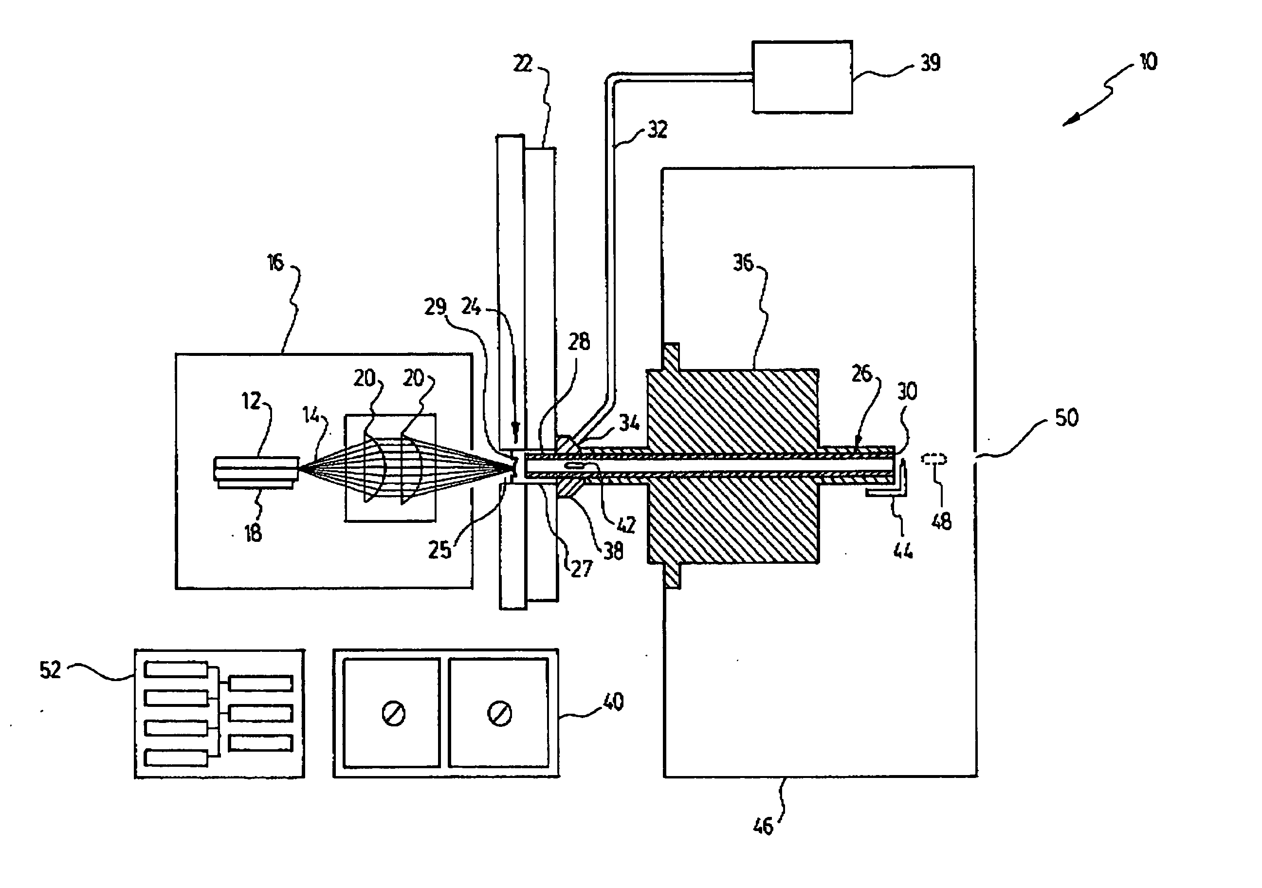
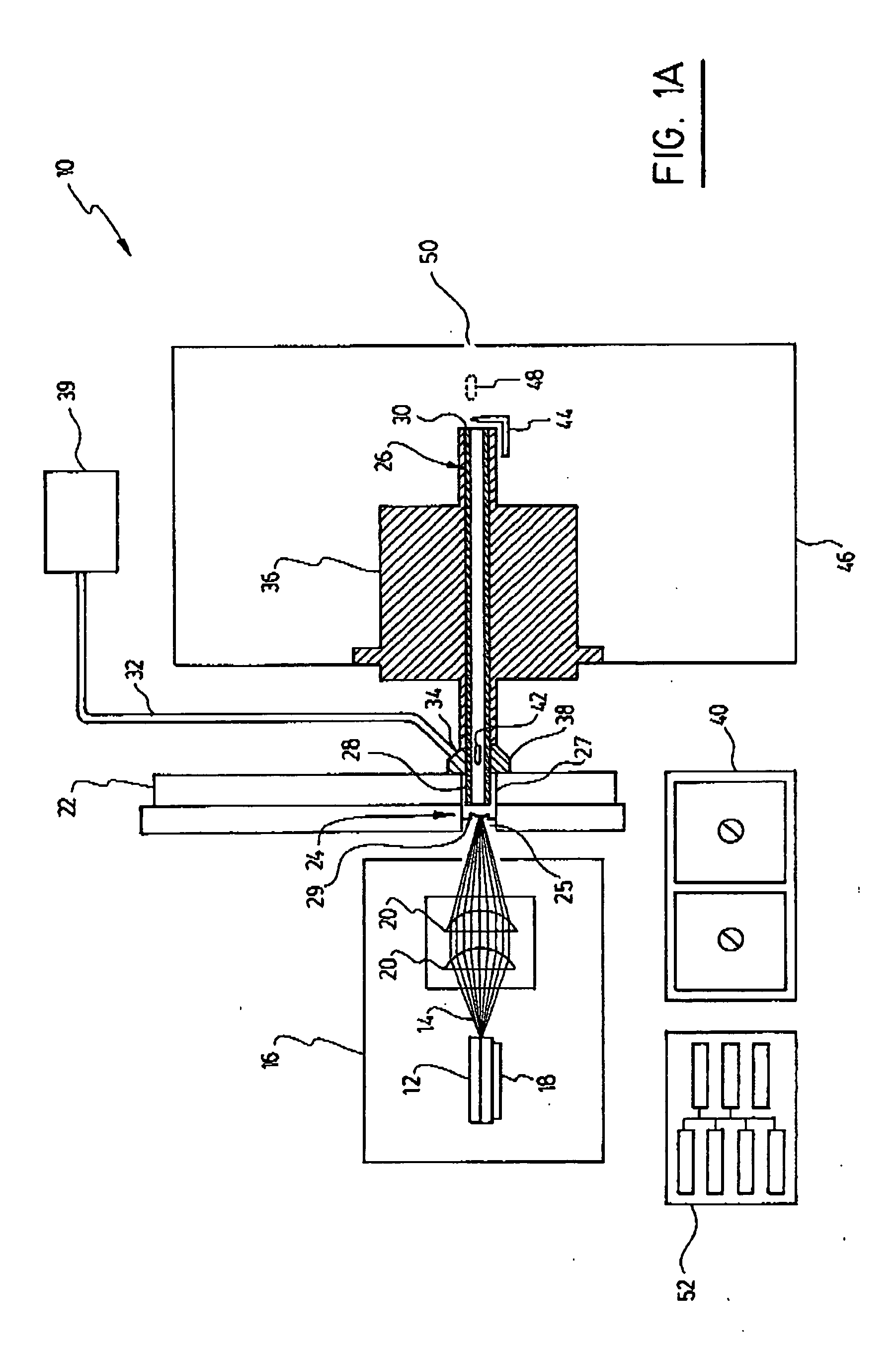
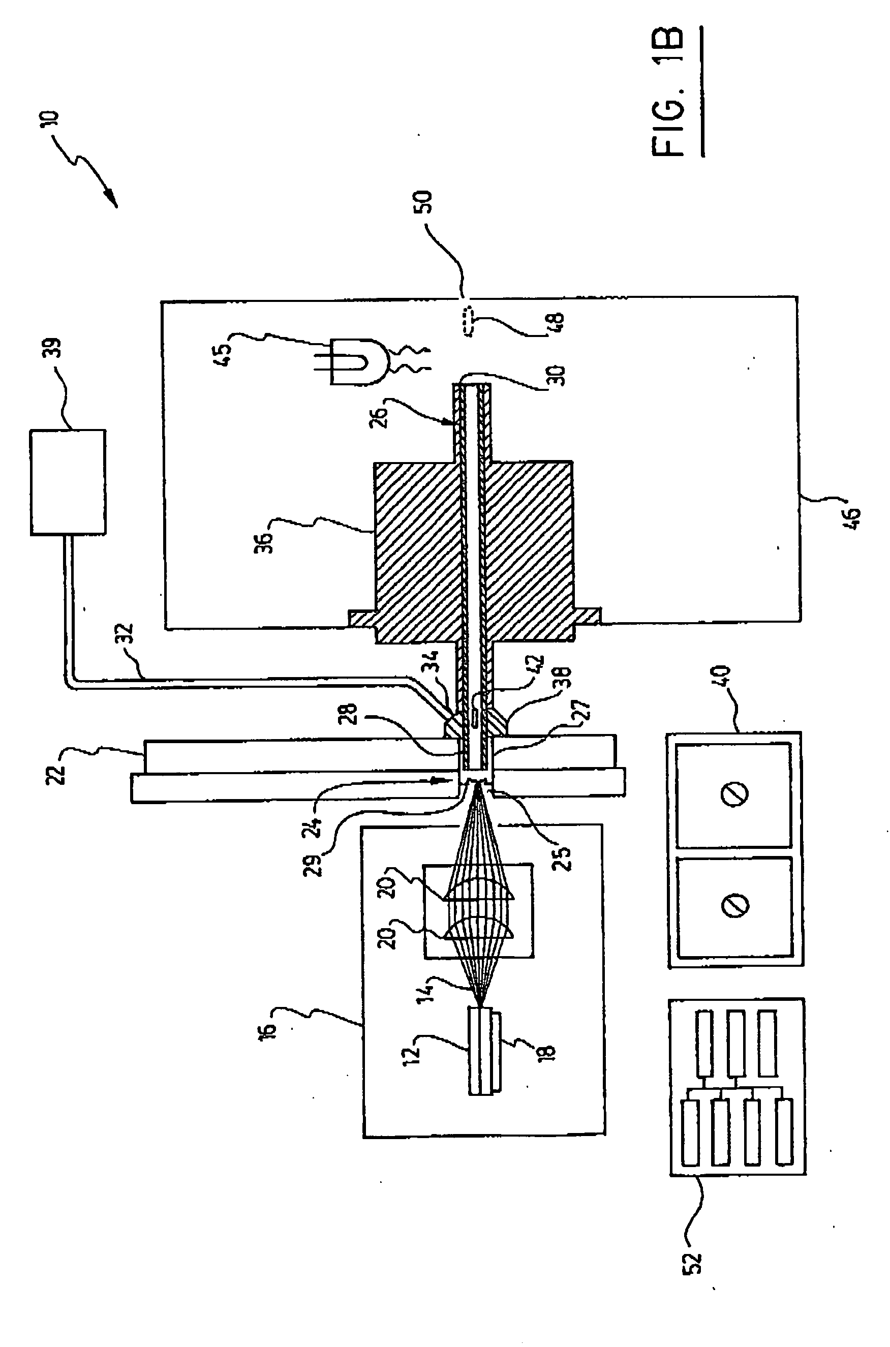
[0019] Generally speaking, a new ionization source at atmospheric pressure, preferably interfaced with mass spectrometry, has been developed in response to industry's needs and requests. In its preferred embodiment, the ionization source is based on a process of thermal laser desorption and thus has been named LDTD (Laser Diode Thermal Desorption). Thermal desorption is induced indirectly by a laser beam without a support matrix-unlike the MALDI technique—and ionization is achieved by a corona discharge without liquid mobile phase—unlike the APCI technique. The LDTD technique being matrix and mobile phase free, cross contamination of samples is virtually eliminated.

[0020] The present invention first provides an apparatus for generating ionized samples. Although the following description is applied to a system allowing the automated sequential generation of ions from a p...


PUM


Abstract

An apparatus and method for regenerating ion samples for a mass spectrometer are provided. Source samples are loaded on a support which is heated by a laser beam, desorbing the sample without ionization. The desorbed sample is carried by a carrier gas flow through a transfer tube, at the output of which it is ionized by corona discharge or photo-ionization. The obtained ionized sample may be analyzed in a mass spectrometer or used to serve any other appropriate purpose.

Description

[0001] This application claims priority to Canadian Application No. 2,480,549 filed Sep. 15, 2004, hereby incorporated by reference herein. FIELD OF THE INVENTION [0002] This invention generally relates to the field of ionization sources, and more specifically concerns an apparatus and method for generating ionized samples through thermal desorption and / or vaporization. BACKGROUND OF THE INVENTION [0003] Nowadays, a large amount of analyses are carried out by combining high resolution separation techniques and mass spectrometry. This combination of scientific instruments has become important in different domains such as those requiring a high quantity of analyses, due partly to the development of new molecules. This is particularly true for fields such as the pharmaceutical, environmental and proteomic industries. [0004] The coupling of chromatography and mass spectrometry now achieves the highest molecular analysis performance. Different coupling and ionisation techniques have been...

Claims


Application Information

Patent Timeline
IPC IPC(8): H01J49/10H01J49/04
CPCH01J49/0463H01J49/168H01J49/049
Inventor PICARD, PIERRELESSARD, DENISL'HEUREUX, ANDRELACOURSIERE, JEANNOBERT, PHILIPPELETARTE, SYLVAINVALLIERES, ALEXANDRETIVERON, ROBERTPAQUIN, REAL
Owner PHYTRONIX TECH
Learn More