Draft inducer blower

Active Publication Date: 2006-03-09
REGAL BELOIT AMERICA
View PDF28 Cites 58 Cited by
  • Summary
  • Abstract
  • Description
  • Claims
  • Application Information

AI Technical Summary

Benefits of technology

[0014] The present invention provides a draft inducer blower for high efficiency furnaces, including a blower housing which facilitates maximum air flow efficiency through the blower housing while having an overall radial dimension which conforms to the industry standard arrangement of mounting holes on the walls of the furnaces. The blower housing generally includes a housing body and housing cover, the housing body including a plurality of mounting lugs, spaced around the outer periphery of the housing body, through which bolts may be inserted to secure the blower housing to the mounting holes in the wall of a furnace. The housing cover and housing body each define portions of a volute which extends around the outer periphery of the blower housing from the cutoff to the exhaust transition of the blower housing. The volute includes a cross-sectional area which substantially continuously increases in the axial direction of the blower housing from the cutoff region to the exhaust transition. In this manner, the blower housing has a radial dimension which conforms to the industry standard mounting hole arrangements for furnaces, yet includes a volute having an increasing cross-sectional area around the blower housing to provide a diffuser section within the blower housing to maximize air flow efficiency.
[0016] Additionally, the housing cover includes an annular ridge which projects upwardly toward the lower plate of the impeller within the blower housing to define a small clearance distance therebetween, which reduces or eliminates the passage of air from the volute between the impeller and the housing cover toward the inlet of the blower housing to substantially seal the air flow within the volute. The housing cover also includes a plurality of radial stiffening ribs which minimize or eliminate inward deflection of the inlet portion of the housing cover when the blower housing is attached to the wall of a furnace, to reduce or eliminate choking of the inlet air as same flows through the inlet opening of the housing cover into the impeller. Further, the housing cover includes a conically-shaped, sloped wall which provides a clearance space between the inlet portion of the housing cover and the impeller to accommodate any minor inward deflection of the inlet portion of the housing cover when the blower housing is attached to the furnace.

Problems solved by technology

In high efficiency furnaces, standard chimney air-draw effects are not sufficient to assure the required air flow through the furnace heat exchangers, and therefore, high efficiency furnaces utilize draft inducer blowers to provide sufficient air flow through the furnace.
However, in draft inducer blowers for high efficiency furnaces, the standard bolt pattern in the wall of the furnace to which the blower housing is attached, imposes a limitation to the diameter and overall size of the blower housing in the radial dimension.
Also, due to the potential for corrosion of the attachment bolts by the exhaust flue gases, the side wall of the blower housing is usually positioned between the attachment bolts and the interior of the blower housing.
A further disadvantage with known blower housings for high efficiency furnaces is the presence of a rather large gap between housing cover 24 and the bottom of impeller 44, shown as distance D1 in FIGS. 3 and 4, which is typically approximately 0.257 inches.

Method used


Image

  • Draft inducer blower
  • Draft inducer blower
  • Draft inducer blower

Examples


Embodiment Construction

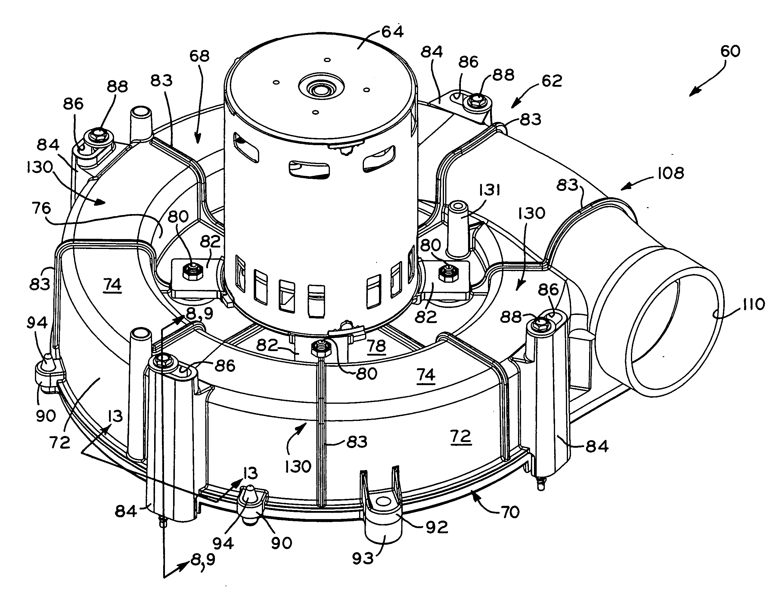
[0037] Referring first to FIG. 5, a blower 60 for a high efficiency furnace according to the present invention is shown. Blower 60 generally includes blower housing 62, electric motor 64 mounted to blower housing 62, and an impeller (FIGS. 6-9), mounted to the output shaft of motor 64 and disposed within blower housing 62. Blower housing 62 generally includes a first housing member or housing body 68, and a second housing member or housing cover 70. Housing body 68 and housing cover 70 may be formed of metal or plastic according to an injection molding process, for example. Suitable plastics for housing body 68 and housing cover 70 include polypropylene or other thermoplastics. Housing body 68 includes a generally cylindrical outer wall 72, an annular top wall 74, an inner wall 76, and a recessed wall 78. Motor 64 is attached to recessed wall 78 by a plurality of fasteners 80 which pass through mounting flanges 82 of motor 64 into recessed wall 78 of housing cover 70. Housing cover ...


PUM


Abstract

A draft inducer blower for high efficiency furnaces, including a blower housing which facilitates maximum air flow efficiency through the blower housing while having an overall radial dimension which conforms to the industry standard arrangement of mounting holes on the walls of the furnaces. The blower housing generally includes a housing body and housing cover, the housing body including a plurality of mounting lugs spaced around the housing body through which bolts may be inserted to secure the blower housing to the mounting holes in the wall of a furnace. The housing cover and housing body each define portions of a volute which extends around the outer periphery of the blower housing from the cutoff region to the exhaust transition of the blower housing. The volute includes a cross-sectional area which substantially continuously increases in the axial direction of the blower housing from the cutoff region to the exhaust transition. In this manner, the blower housing has a radial dimension which conforms to the industry standard mounting hole arrangements for furnaces, yet includes a volute having an increasing cross-sectional area around the blower housing to provide a diffuser section within the blower housing to maximize air flow efficiency. The housing cover is positioned close to the impeller periphery to prevent recirculation. The housing cover is provided with a conical section and ribbing to minimize assembly-caused inlet deflection and to optimize air flow.

Description

BACKGROUND OF THE INVENTION [0001] 1. Field of the Invention [0002] The present invention relates to air moving devices, and in particular, to blowers of the type which are used with high efficiency (e.g., 90% or higher efficiency) furnaces for drawing air from outside of a building into the furnace to support combustion and to expel combustion exhaust products outside of the building. More particularly, the present invention relates to a blower which provides increased air flow through the blower and decreased blower noise while maintaining an overall diameter for the housing of the blower which conforms to, and is compatible with, industry standard mounting bolt patterns on furnaces for attachment of blower housings. [0003] 2. Description of the Related Art [0004] In high efficiency furnaces, standard chimney air-draw effects are not sufficient to assure the required air flow through the furnace heat exchangers, and therefore, high efficiency furnaces utilize draft inducer blowers...

Claims


Application Information

Patent Timeline
IPC IPC(8): F04D29/44
CPCF04D29/626F04D29/4233
Inventor PLATZ, JOHN A.
Owner REGAL BELOIT AMERICA
Why Eureka
Try Eureka