
Rotating containment tool for contaminated sediment remediation in an aqueous environment

a technology of contaminated sediment and containment tool, which is applied in the field of tools for remediation of contaminated sediment in an aqueous environment, can solve the problems of affecting the overall effectiveness and efficiency of each active management strategy, and affecting the overall effectiveness and efficiency of the respective approach. , to achieve the effect of preventing the release of contaminants and reducing the instability of the wall

Inactive Publication Date: 2006-03-09
CHESNER WARREN +1
View PDF6 Cites 15 Cited by
  • Summary
  • Abstract
  • Description
  • Claims
  • Application Information

AI Technical Summary

Benefits of technology

[0022] The object of the invention presented in this patent is to provide a subaqueous contaminated sediment remediation tool that can prevent the migration of contaminants during sediment removal, capping and in-situ treatment operations and provide for secure and precise placement of capping material. SUMMARY OF THE INVENTION

Problems solved by technology

Planners and engineers responsible for designing remediation strategies for such subaqueous contaminated sediment sites have a limited number of options from which to choose.
Each of the active management strategies has some serious limitations with respect to the overall effectiveness and efficiency of the respective approach.
With respect to sediment removal or dredging technology, one of the more notable limitations is the unavoidable disruption of the subsurface sediment and loss of sediment stability that occurs during the dredging process, and the resulting migration of contaminants from the dredge site to downstream locations.
In addition, recent data suggest that there is significant uncertainty as to whether dredging alone can adequately remediate subaqueous contaminated sediment sites.
There are several limitations associated with capping technology.
Paradoxically, while adequate mixing is necessary to effectively deliver reagents to a subaqueous contaminated sediment, such mixing will destabilize the sediment resulting in similar, but perhaps more aggravated, dispersion problems than those associated with dredging technology.
In summary, each of the active remediation approaches (i.e., sediment removal, capping and in-situ treatment) has significant limitations.
Dredging and in-situ treatment can be expected to induce subsurface instability and contaminant dispersion during operations.
Capping technology is limited by the ability to place a capping material in a precise and accurate manner, with minimal subsurface disturbance at a designated location and ensure that the cap will remain in-place and will not be impacted by the erosive forces in the waterway.
Silt curtain use is limited to waterways with low currents (typically less than one knot).
Fixed sheet pile installation severely limits the mobility and flexibility of dredging operations.
This means that all equipment (dredging and solids handling barges) will usually be trapped inside the sheet pile barrier for the duration of the project (unless the dredging equipment can be deployed on land).
Finally, if adequate space is not available, navigation on the waterway can be hampered for an extended time (until the operation is completed).
In addition and perhaps most problematic is the fact that both silt curtain and fixed sheet pile containment suffer from the critical environmental limitation that the contained sediments present in the destabilized sediment layer are free to migrate from the site once the respective barriers are removed.
While clamshell buckets, vacuum heads, and even backhoes have been employed in the removal of subaqueous sediments, rotating digging tools such as augers have rarely been used.
This can happen when wet or cohesionless materials are encountered.
Caisson dredging technology is limited however by the cumbersome, slow and expensive operational sequence, primarily associated with driving a long, large diameter steel caisson into the subaqueous sediment to prepare a containment area for each excavation.

Method used


Image

  • Rotating containment tool for contaminated sediment remediation in an aqueous environment
  • Rotating containment tool for contaminated sediment remediation in an aqueous environment
  • Rotating containment tool for contaminated sediment remediation in an aqueous environment

Examples


Embodiment Construction

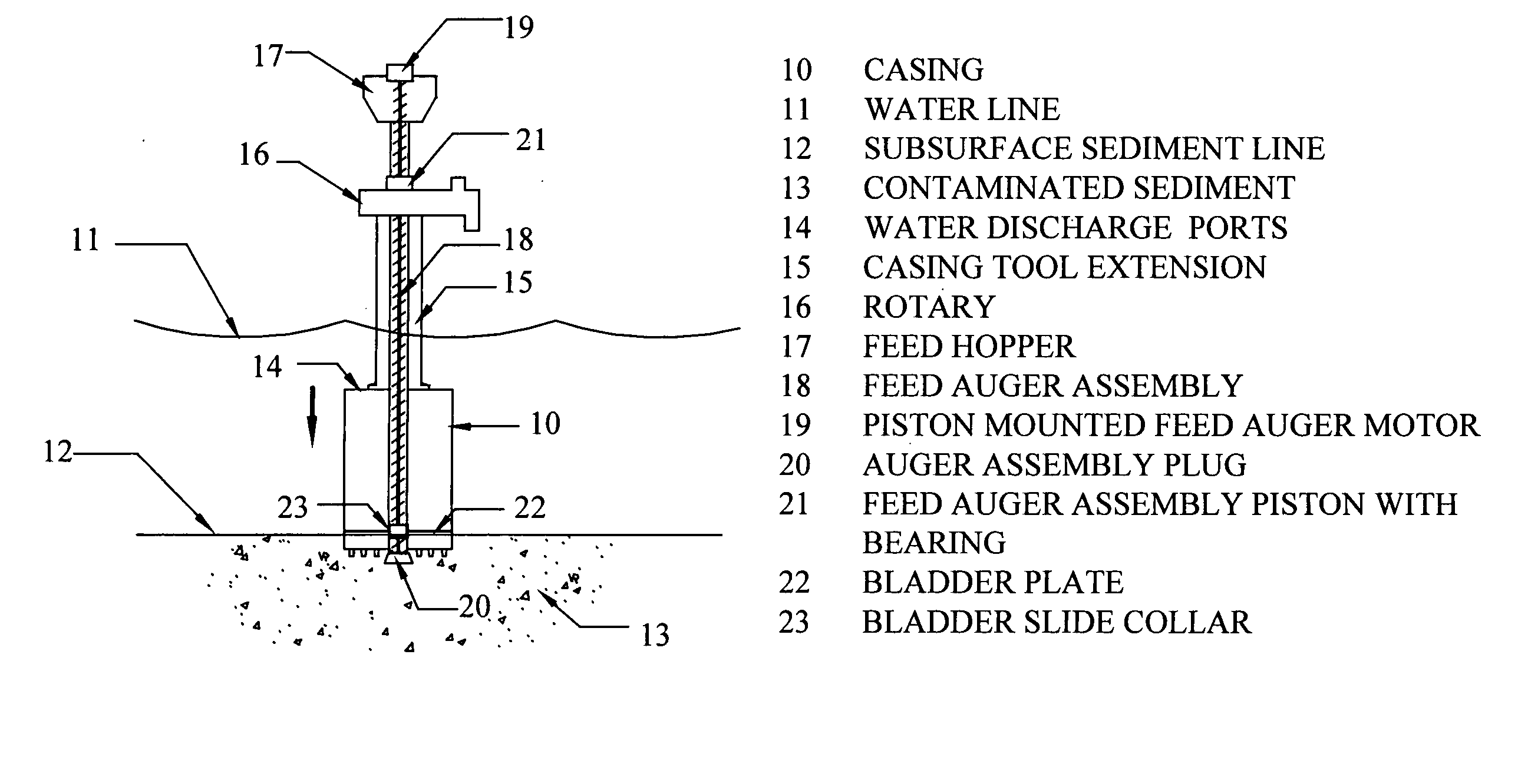
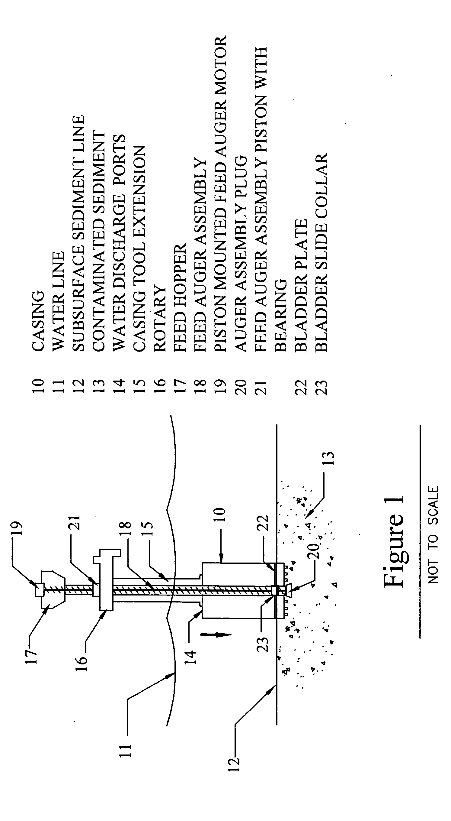
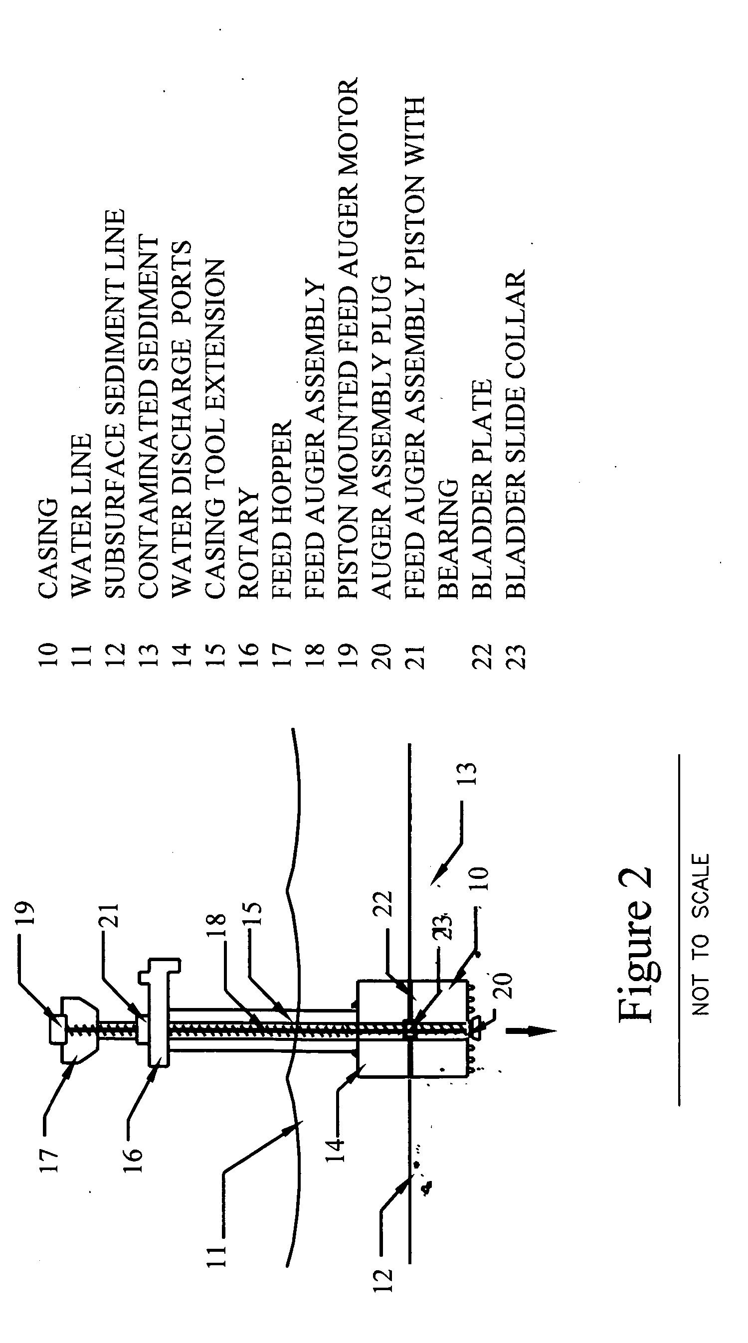
[0057]FIG. 1 depicts the rotating containment tool in an excavation mode of operation, where the casing 10 has descended below the water line 11 and has just penetrated the subsurface sediment line 12 to remove contaminated sediments 13. The casing 10 is equipped with pressure water discharge ports 14 at the top that provide the means to relieve internal pressure when sediment is forced into the housing.

[0058] The casing 10 is connected by means of a casing tool extension 15 to a rotary 16, which is driven by a rotary drilling machine (not shown) that rotates the casing tool extension 15 and the casing 10.

[0059] Extending from the bottom of the casing 10, up through the feed hopper 17, the inventors have incorporated a feed auger assembly 18. The feed auger assembly 18 houses an auger inside that delivers backfill or capping material to the excavated hole. The feed auger assembly 18 is housed inside the containment tool extension 15 from the top of casing 10 to the rotary 16. The ...


PUM


Abstract

A rotating cylindrical containment tool that removes contaminated sediment and prevents the dispersion of contaminated sediments during excavation. The tool casing is rotated and is forced down into the sediment whereby the sediment rises up into the interior of the casing. Water flows into and out of the casing based on external and internal pressures. After the sediment rises into the cylindrical casing a feed auger assembly extending therefrom is utilized to deliver materials and / or cap the excavated void space in the sediment. Alternatively, the rotating containment tool prevents the dispersion of contaminated sediments and treats contaminated sediment in situ with treatment reagents, in the sub-aqueous environment.

Description

RELATED APPLICATIONS [0001] This application is based upon provisional application No. 60 / 607,726 filed Sep. 12, 2004 and claims priority benefit under 35 U.S.C. 119(e) therefrom.FIELD OF THE INVENTION [0002] This application relates to tools for remediation of contaminated sediment in an aqueous environment. BACKGROUND OF THE INVENTION [0003] In recent years, the ecological impacts associated with the presence of subaqueous contaminated sediments in many lakes, rivers and estuaries in the U.S. have reached significant severity to warrant regulatory and in some cases enforcement actions against responsible parties, by Federal, state, and local authorities, to remediate the problem. Planners and engineers responsible for designing remediation strategies for such subaqueous contaminated sediment sites have a limited number of options from which to choose. The primary options available fall into three categories: 1) natural attenuation, 2) sediment removal, and 3) in-situ management. [...

Claims


Application Information

Patent Timeline
IPC IPC(8): B65G5/00B09C1/00
CPCE02F3/06B09C1/00
Inventor CHESNER, WARRENMAXWELL, GREGORY W.
Owner CHESNER WARREN
Learn More