
Method for controlling operation of a child or neighbor network

a technology for controlling the operation of a child or neighbor network, which is applied in the direction of loop networks, data switching networks, multiplex communication, etc., can solve the problems of affecting the system, unable to transmit for the duration of the super-frame, and the failure of the receiving device in acquiring and receiving the signal, so as to avoid increasing the chance that the active device loses coordination with each other

Inactive Publication Date: 2006-03-09
NORTH STAR INNOVATIONS
View PDF15 Cites 60 Cited by
  • Summary
  • Abstract
  • Description
  • Claims
  • Application Information

AI Technical Summary

Benefits of technology

[0045] Another object of the present invention is to provide a way of adjusting pseudo static time slots for active devices without interrupting the flow of information between the active devices, and without increasing the chance of the active devices losing their coordination with each other.

Problems solved by technology

Furthermore, it cannot transmit for the duration of the super-frame because it does not know when it is permitted to transmit.
This is detrimental to the system because it leads to interruptions in data transmission.
For example if device one 321 and device four 324 both try and transmit data at the same time, this data may collide and cause the receiving devices to fail in acquiring and receiving the signal.
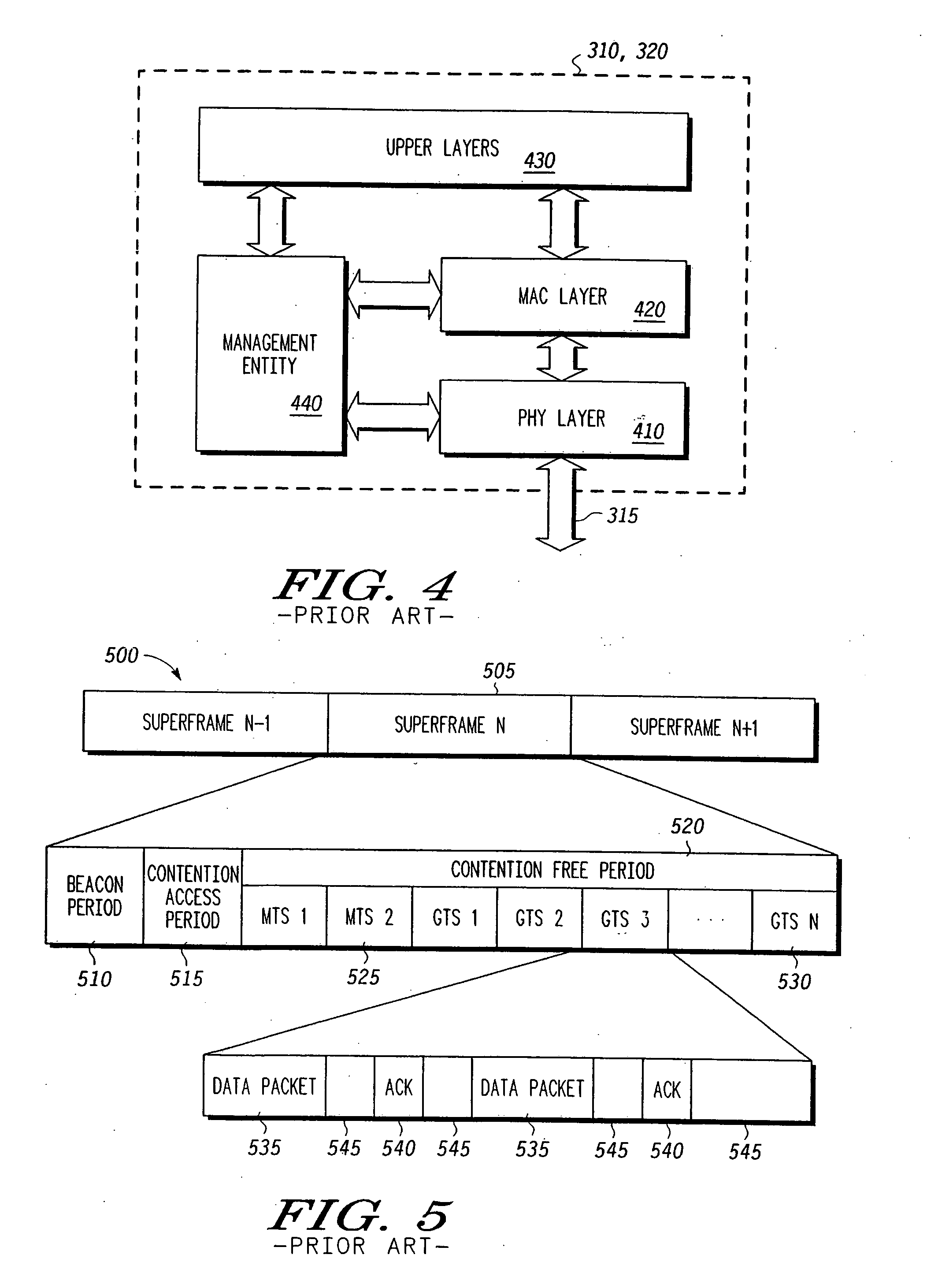
This can lead to problems if a device 321-325 misses the beacon 510.
A problem with this system, however, is that it can lead to significant transmission errors if the devices 321-325 cannot properly receive the beacons 510.
This could lead to a dead air rate proportional to the beacon rate.
Such an error rate would be unacceptable for many applications, and would require additional buffering to make up for the losses, which would serve to increase the cost of the device 321-325.
A problem with using static GTSs 530 is that the assigned time slots 530 can become poorly allocated.
This can cause a loss in transmission speed because of wasted time, and may make it difficult to accommodate adjacent networks that may need time allocated in larger durations.

Method used


Image

  • Method for controlling operation of a child or neighbor network
  • Method for controlling operation of a child or neighbor network
  • Method for controlling operation of a child or neighbor network

Examples


Embodiment Construction

[0076] As shown above, static time slots allow for certain advantages, but incur certain disadvantages. Primarily they prevent the interruptions in the data transmission stream because of corrupt beacons 510, but at a cost of slot assignment flexibility. Applicants will discuss below several alternative embodiments using static slots and pseudo-static slots.

Overlapping Networks Using Static Slots

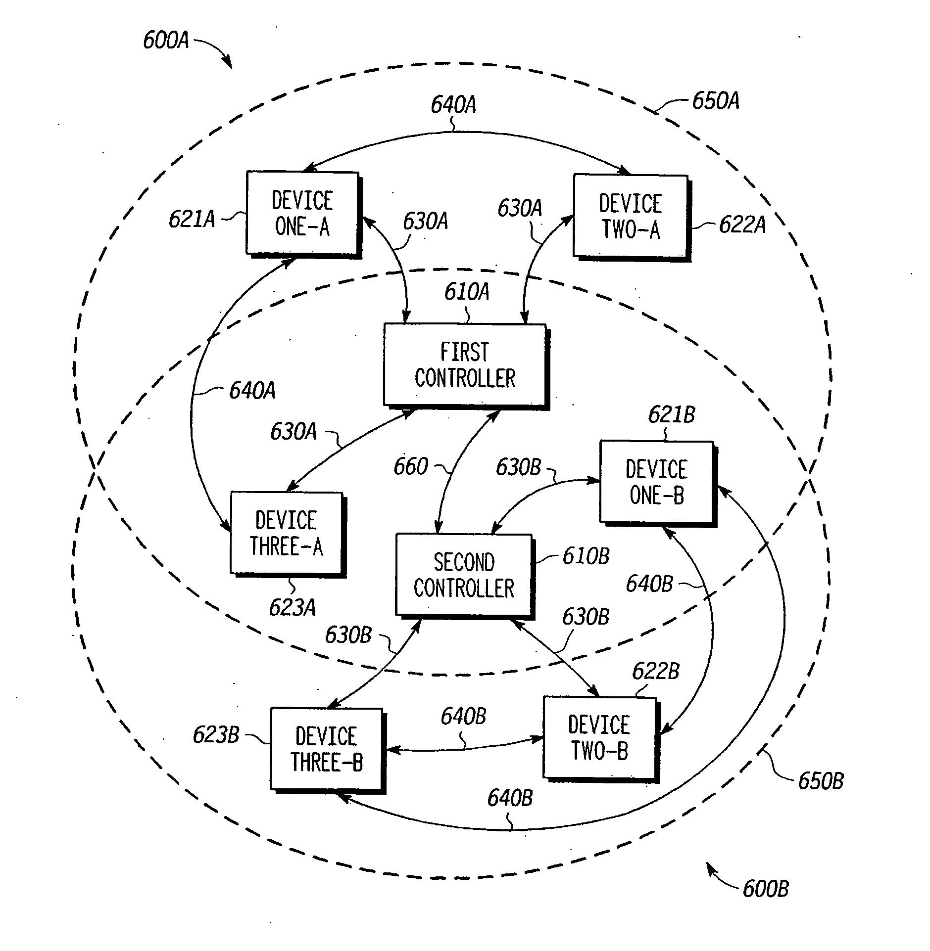
[0077] Applicants present an additional implementation for static time slots—sharing of available air transmission time in overlapping networks. Consider the situation where two networks are located such that their transmission area overlaps. For example, a user may have one network in one part of his house and another network in another part of his house. These networks may overlap in part or in whole with each other's transmission area. Regardless, where they overlap, there is a potential for collisions and interference.

[0078]FIG. 6 is a block diagram of two overlapping wireless networ...


PUM


Abstract

A wireless network is provided that uses pseudo-static time slots. These time slots remain fixed in time unless and until a network controller specifically changes them and the network controller subsequently receives confirmation of the change. Times and durations of the pseudo-static time slots are only changed in small steps as each relevant device in the network acknowledges the step. To aid in allowing full coverage even during a change of active devices, when a transmitter and receiver are moved to a new time slot, the receiver is set to listen to both the old and the new time slots until the transmitter confirms that it has made the switch.

Description

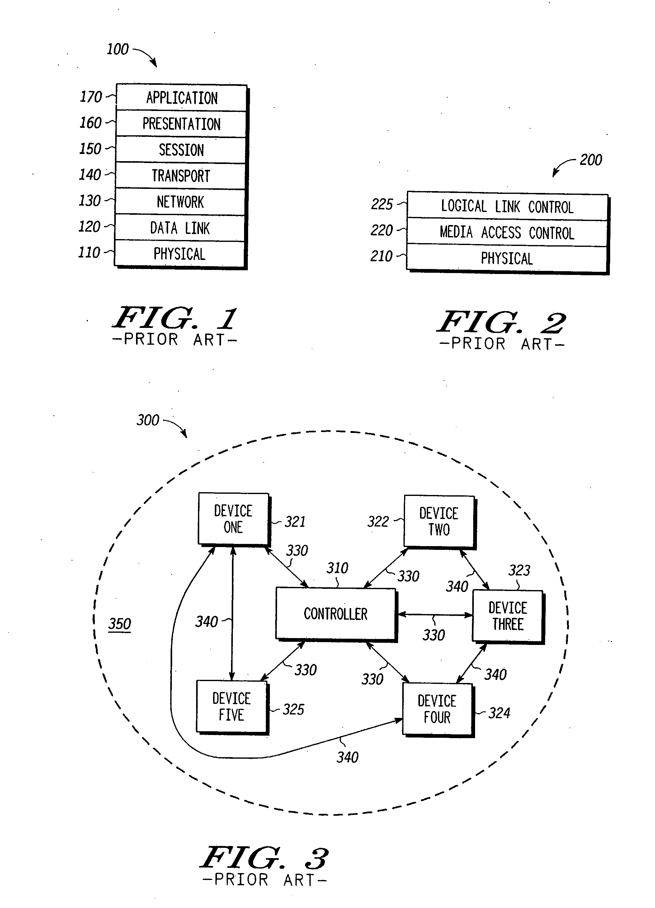
BACKGROUND OF THE INVENTION [0001] The present invention relates to wireless personal area networks and wireless local area networks. More particularly, the present invention relates to systems, methods, devices, and computer program products for controlling transmitted power and transmission rate in a wireless personal area network or wireless local area network environment. [0002] The International Standards Organization's (ISO) Open Systems Interconnection (OSI) standard provides a seven-layered hierarchy between an end user and a physical device through which different systems can communicate. Each layer is responsible for different tasks, and the OSI standard specifies the interaction between layers, as well as between devices complying with the standard. [0003]FIG. 1 shows the hierarchy of the seven-layered OSI standard. As seen in FIG. 1, the OSI standard 100 includes a physical layer 110, a data link layer 120, a network layer 130, a transport layer 140, a session layer 150,...

Claims


Application Information

Patent Timeline
Patent Type & Authority Applications(United States)
IPC IPC(8): H04L12/43H04B7/212H04J3/16H04L12/28H04L12/56
CPCH04W28/04H04W72/12H04W84/12H04W74/04H04W74/0808H04W74/02
Inventor SHVODIAN, WILLIAM M.
Owner NORTH STAR INNOVATIONS
Learn More