
Methods and apparatus for continuous coking refining

a technology of coking and refining equipment, which is applied in the direction of mechanical conveying coke ovens, stationary retorts, thermal non-catalytic cracking, etc., can solve the problems of difficult to achieve true continuous process, difficult to process coke at the same time, and difficult to achieve coke. , to achieve the effect of constant and continuous refinemen

Inactive Publication Date: 2006-03-09
WYOMING THE UNIV OF RES CORP +1
View PDF16 Cites 0 Cited by
  • Summary
  • Abstract
  • Description
  • Claims
  • Application Information

AI Technical Summary

Benefits of technology

[0009] The present invention provides a continuous refining process which permits the intentional formation of coke from the material to be processed while acting to separate and perhaps create a greater quantity of refined products. In one embodiment, the invention utilizes an inclined auger with a medium such as sand in which the raw material is heated past the coking point. The auger then continuously moves the coke out of the bed so that constant and continuous refinement can occur.
[0010] Accordingly, it is one of the many goals of the present invention to provide a system through which continuous refining can occur even while permitting coke to form. In achieving such a goal the invention provides refinement in one system but with multiple zones so that the continuous process can be efficiently conducted.

Problems solved by technology

Coke can be problematic because it is a very hard and relatively untransformable substance which usually binds to its container when formed.
Great pains are often taken in processing relative to coke.
By its very nature, a true continuous process is difficult to achieve.
In addition, because of the larger capital expense of such handling, at present only large refineries currently utilize coking as the principal method of upgrading heavy crude oils.
Thus, while desirable for efficiency, smaller refineries have not been able to practically utilize coking processes on a commercially viable basis.
In spite of this need, however, a solution to the precipitous formation of coke and availability of coking processes has not been available to the degree commercially desired.
In spite of this long felt need, the appropriate process as not been available, however.

Method used


Image

  • Methods and apparatus for continuous coking refining
  • Methods and apparatus for continuous coking refining
  • Methods and apparatus for continuous coking refining

Examples


Embodiment Construction

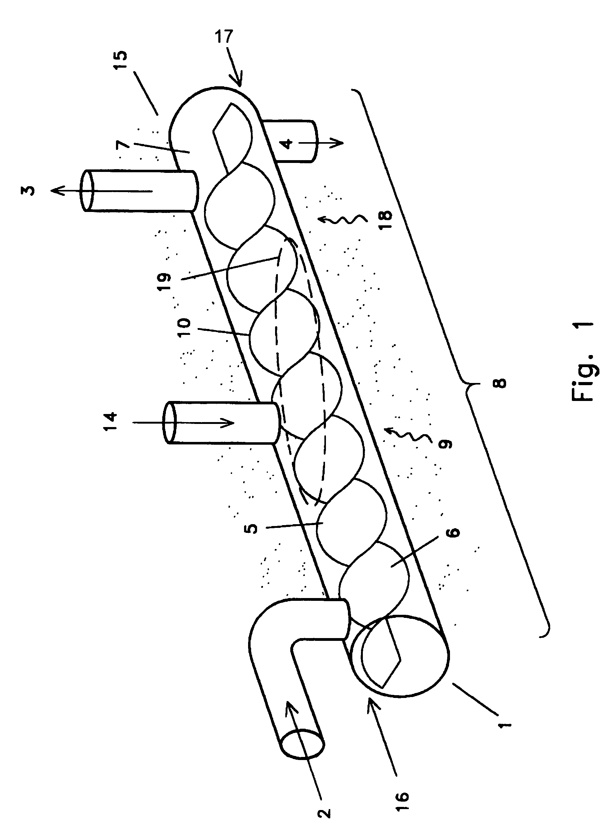
[0019] As can be seen from the drawings, the basic concepts of the present invention may be embodied in many different ways. FIG. 1 shows a schematic of an inclined auger-type of refining apparatus according to the present invention. This can be considered one of the many key components to an improved refining system. As an important feature of one embodiment, the system is designed not only to be able to accept heavy hydrocarbon containing material, it can do it on a continuous basis. As shown in FIG. 1, the refining apparatus may include a pyrolyzer (1) having a process container (5) within which refining can occur. The pyrolyzer (1) may have some type of input (2) through which material to be processed may travel. In keeping with one of the goals of the invention, the input (1) may be a continuous input such that material is provided into the pyrolyzer (1) at the same rate at which it is processed. The processing of the material may, of course, result in refined products which ma...


PUM

PropertyMeasurementUnit
temperatureaaaaaaaaaa

Abstract

A system for refining hydrocarbon containing materials in a continuous coking mode may provide a pyrolyzer (1) which may be inclined to effect a liquid seal between a liquid conduction environment (6) and a gaseous conduction environment (7). A heat source (9) may heat the material past the coking point and the system may include a screw or auger (10) which can continuously remove the coke while simultaneously outputting refined products.

Description

[0001] This application is a continuation of U.S. patent application Ser. No. 10 / 130,921, filed May 24, 2002, which was the U.S. national stage of International Application No. PCT / US00 / 32029, filed Nov. 21, 2000, which claimed the benefit of U.S. Provisional Patent Application No. 60 / 167,337, filed Nov. 24, 1999, and U.S. Provisional Patent Application No. 60 / 167,335, filed Nov. 24, 1999, each hereby incorporated by reference.I. TECHNICAL FIELD [0002] The present invention relates to methods and apparatus for refining heavy oils such as in transforming heavy oils into lighter, or higher quality components which are more commercially useful. II. BACKGROUND ART [0003] Everyone is aware of the importance that oil and other such materials have on today's world. They represent an important topic from a wide range of perspectives ranging from environmental to economic to political. At a chemical level, these materials are significant because the substances of which they are composed have...

Claims


Application Information

Patent Timeline
Patent Type & Authority Applications(United States)
IPC IPC(8): C10B1/08C10B1/00C10B7/10C10B53/06C10B55/00C10G9/00C10G9/02C10G9/04C10G9/20
CPCC10B7/10C10G9/005C10B55/00C10B53/06
Inventor BRECHER, LEE E.JOHNSON, LYLE A. JR.SETHI, VIJAY K.
Owner WYOMING THE UNIV OF RES CORP
Learn More