Optimized liquid-phase oxidation

Inactive Publication Date: 2006-03-02
GRUPO PETROTEMEX DE C V
View PDF99 Cites 23 Cited by
  • Summary
  • Abstract
  • Description
  • Claims
  • Application Information

AI Technical Summary

Benefits of technology

[0010] It is, therefore, an object of the present invention to provide a more effective and economical liquid-phase oxidation reactor and process.
[0011] Another object of the invention is to provide a more effective and economical reactor and process for the liquid-phase catalytic partial oxidation of para-xylene to terephthalic acid.
[0012] Still another object of the invention is to provide a bubble column reactor that facilitates improved liquid-phase oxidation reactions with reduced formation of impurities.
[0013] Yet another object of the invention is to provide a more effective and economical system for producing pure terephthalic acid (PTA) via liquid-phase oxidation of para-xylene to produce crude terephthalic acid (CTA) and subsequently, purifying the CTA to PTA.
[0014] A further object of the invention is to provide a bubble column reactor for oxidizing para-xylene and producing a CTA product capable of being purified without requiring heat-promoted dissolution of the CTA in water, hydrogenation of the dissolved CTA, and / or multi-step crystallization of the hydrogenated PTA.
[0021] A still further embodiment of the present invention concerns a system for producing and purifying terephthalic acid. The system includes a reactor and a deaeration vessel. The reactor facilitates the production of crude terephthalic acid in a three-phase reaction medium. The reactor defines a reactor outlet for discharging at least the solid and liquid phases of the reaction medium from the reactor. The deaeration vessel facilitates the disengagement of the gas phase of the three-phase reaction medium from the solid and liquid phases of the three-phase reaction medium to thereby provide a substantially deaerated slurry. The deaeration vessel is coupled in fluid flow communication with the reactor outlet. The deaeration vessel defines a reaction medium inlet for receiving the three-phase reaction medium and a slurry outlet for discharging the deaerated slurry. The slurry outlet is located lower than the reaction medium inlet. The deaeration vessel comprises one or more upright sidewalls defining an internal deaeration zone vertically disposed between the reaction medium inlet and the slurry outlet. The deaeration zone has a maximum height in the range of from about 0.3 to about 5 meters and a maximum horizontal cross-sectional area in the range of from about 0.02 to about 3 meters squared. The purification system receives the deaerated slurry from the slurry outlet and purifies the deaerated slurry.

Problems solved by technology

If the liquid phase of the multi-phase reaction medium contains an insufficient concentration of molecular oxygen (i.e., if certain portions of the reaction medium are “oxygen-starved”), undesirable side-reactions can generate impurities and / or the intended reactions can be retarded in rate.
If the liquid phase of the reaction medium contains too little of the oxidizable compound, the rate of reaction may be undesirably slow.
Further, if the liquid phase of the reaction medium contains an excess concentration of the oxidizable compound, additional undesirable side-reactions can generate impurities.
For example, CSTRs have a relatively high capital cost due to their requirement for expensive motors, fluid-sealed bearings and drive shafts, and / or complex stirring mechanisms.
Further, the rotating and / or oscillating mechanical components of conventional CSTRs require regular maintenance.
The labor and shutdown time associated with such maintenance adds to the operating cost of CSTRs.
However, even with regular maintenance, the mechanical agitation systems employed in CSTRs are prone to mechanical failure and may require replacement over relatively short periods of time.
CTA contains relatively high levels of impurities (e.g., 4-carboxybenzaldehyde, para-toluic acid, fluorenones, and other color bodies) that render it unsuitable as a feedstock for the production of PET.
Although effective, this type of conventional purification process can be very expensive.
Individual factors contributing to the high cost of conventional CTA purification methods include, for example, the heat energy required to promote dissolution of the CTA in water, the catalyst required for hydrogenation, the hydrogen stream required for hydrogenation, the yield loss caused by hydrogenation of some terephthalic acid, and the multiple vessels required for multi-step crystallization.

Method used


Image

  • Optimized liquid-phase oxidation
  • Optimized liquid-phase oxidation
  • Optimized liquid-phase oxidation

Examples


example 1

[0279] This is an operational example from a commercial oxidation of para-xylene in a bubble column reactor. This example demonstrates, for example, that large vertical gradients exist for concentrations of para-xylene when appropriate geometric and process conditions are employed according to aspects of the current invention.

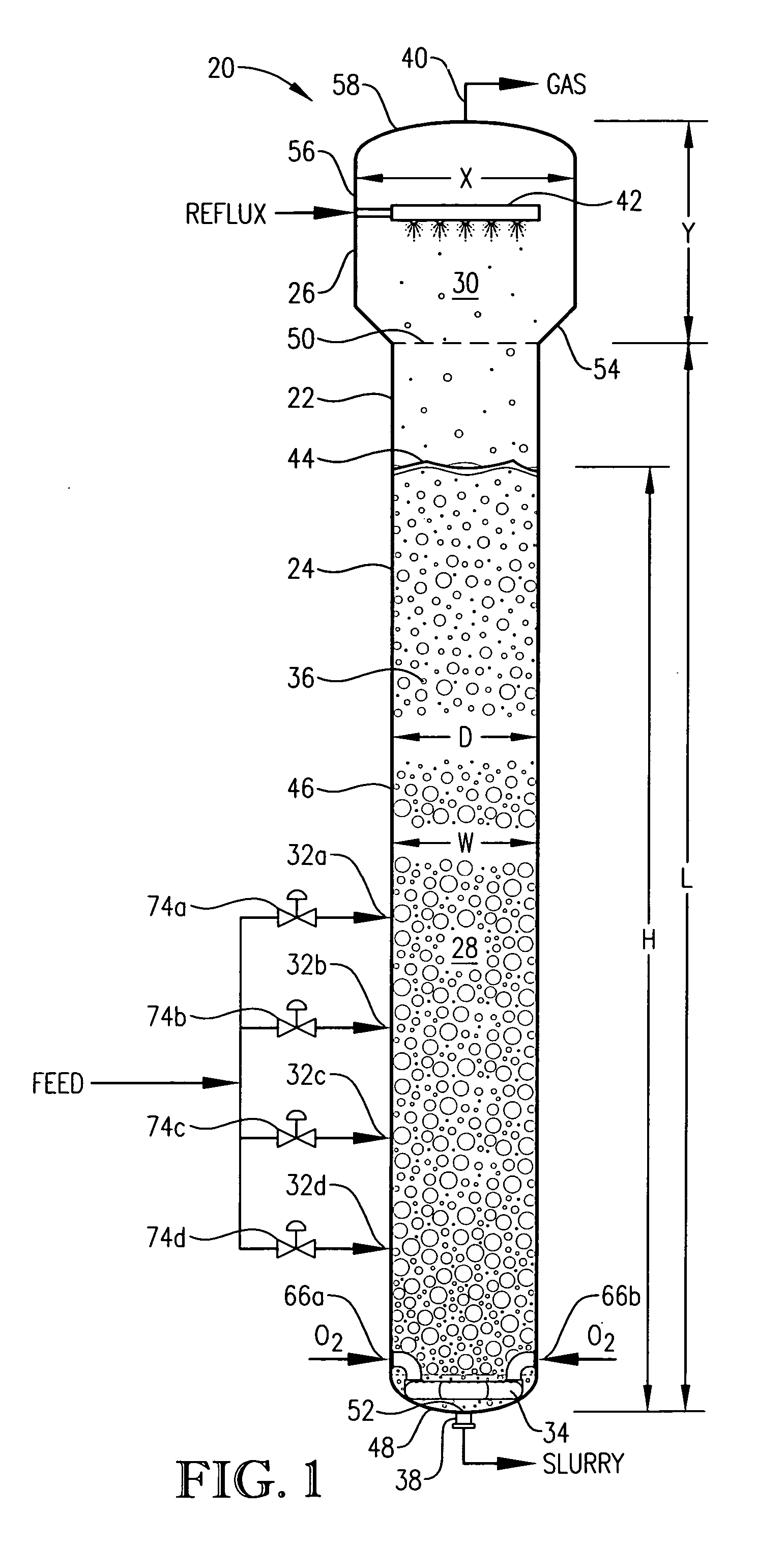
[0280] This example employed a commercial bubble column oxidizer vessel having a nearly vertical, essentially cylindrical body with an inside diameter of about 2.44 meters. The height of the bubble column oxidizer vessel was about 32 meters from lower tangent line (TL) to upper TL. The vessel was fitted with about 2:1 elliptical heads at the top and bottom of the cylinder. The operating level was about 25 meters of reaction medium above the lower TL. The feed rate of commercial-purity para-xylene was effectively steady at a rate of about 81 kilograms per minute, entering the reaction vessel through a circular hole located in the wall of the cylindrical section...

examples 2-5

[0287] Examples 2-5 are calculational models of bubble column reactors either identical to the reactor of Example 1 or generally similar with specified improvements. The computational fluid dynamics (CFD) modeling performed to generate Examples 2-5 was performed in accordance with the modeling method disclosed in co-pending U.S. Pat. App. Ser. No. 60 / 594,774 entitled “Modeling of Liquid-Phase Oxidation,” the entire disclosure of which is expressly incorporated herein by reference.

[0288] In Examples 2-5, the CFD modeling is performed using CFX release 5.7 (ANSYS, Inc. 275 Technology Drive, Canonsburg, Pa. 15317). Examples 2-5 comprise upwards of about 100,000 discrete spatial computational cells each. Time steps useful in Examples 2-5 are less than 0.1 seconds. Multiple bubble sizes ranging in diameter from about 0.005 to about 0.20 meters prove useful to tune the CFD model to approximate closely to the average bubble hold-up assessed via differential pressure measurement, to the ve...

example 2

[0291] This example develops calculations pertinent to the mechanical configuration of Example 1 and sets a comparative basis for Examples 3 and 4. In this example, the mechanical configuration of the bubble column reactor is identical to Example 1, having a 0.076-meter circular diameter entry hole through the reaction vessel wall for the feed stream comprising para-xylene and filtrate solvent. The feed rate of para-xylene is about 1.84 kilograms per second, higher than in Example 1. The feed rate of filtrate solvent fed intimately commingled with the para-xylene is about 18.4 kilograms per second. The superficial velocity of the combined stream of para-xylene plus filtrate solvent entering through the wall hole is thus about 4 meters per second. The feed rate of reflux solvent in to the gas disengaging head space is 12.8 kilograms per second. The feed rate of compressed air through the oxidant sparger is about 9 kilograms per second. The solids content of the reaction slurry is abo...


PUM

PropertyMeasurementUnit
Temperatureaaaaaaaaaa

Abstract

Disclosed is an optimized process and apparatus for more efficiently and economically carrying out the liquid-phase oxidation of an oxidizable compound. Such liquid-phase oxidation is carried out in a bubble column reactor that provides for a highly efficient reaction at relatively low temperatures. When the oxidized compound is para-xylene and the product from the oxidation reaction is crude terephthalic acid (CTA), such CTA product can be purified and separated by more economical techniques than could be employed if the CTA were formed by a conventional high-temperature oxidation process.

Description

CROSS-REFERENCE TO RELATED APPLICATIONS [0001] This application claims priority to U.S. Provisional Application Serial No. 60 / 606,618, filed Sep. 2, 2004 and 60 / 631,326, filed Nov. 29, 2004, the disclosures of which are incorporated herein by reference in their entirety.FIELD OF THE INVENTION [0002] This invention relates generally to a process for the liquid-phase, catalytic oxidation of an aromatic compound. One aspect of the invention concerns the partial oxidation of a dialkyl aromatic compound (e.g., para-xylene) to produce a crude aromatic dicarboxylic acid (e.g., crude terephthalic acid), which can thereafter be subjected to purification and separation. Another aspect of the invention concerns an improved bubble column reactor that provides for a more effective and economical liquid-phase oxidation process. BACKGROUND OF THE INVENTION [0003] Liquid-phase oxidation reactions are employed in a variety of existing commercial processes. For example, liquid-phase oxidation is curr...

Claims


Application Information

Patent Timeline
IPC IPC(8): C07C51/265
CPCB01J4/002B01J10/002C07C51/265B01J19/1806B01J19/1862B01J19/1875B01J19/1881B01J19/2405B01J19/245B01J19/246B01J19/2465B01J19/26B01J2219/00006B01J2219/0004B01J2219/00105B01J2219/00182B01J2219/00186C07C63/26
Inventor WONDERS, ALAN GEORGEDE VREEDE, MARCELPARTIN, LEE REYNOLDSSTRASSER, WAYNE SCOTT
Owner GRUPO PETROTEMEX DE C V
Why Eureka
Try Eureka