
Substrate reversing device, substrate transporting device, substrate processing device, substrate reversing method, substrate transporting method and substrate processing method

a substrate and reversing technology, applied in the direction of thin material processing, charge manipulation, furnaces, etc., can solve the problems of increasing the parts count, affecting the formation of a pattern on the substrate, and requiring a long time, so as to achieve a small number of steps, reduce the size, and reduce the effect of reversing

Active Publication Date: 2006-03-02
DAINIPPON SCREEN MTG CO LTD
View PDF18 Cites 58 Cited by
  • Summary
  • Abstract
  • Description
  • Claims
  • Application Information

AI Technical Summary

Benefits of technology

[0032] An object of the present invention is to provide a substrate reversing device capable of reversing a substrate reliably with a small number of steps and simple structure while enabling a smaller size.
[0033] Another object of the present invention is to provide a method capable of reversing a substrate reliably with a small number of steps, whereby the structure of a substrate reversing device can be made simpler and smaller.
[0034] Still another object of the present invention is to provide a substrate transporting device capable of transporting a substrate while performing the process of reversing the substrate in a short time, using a simple structure without upsizing a substrate reversing device.

Problems solved by technology

During the above-mentioned variety of processes, the particles attached on the back surface of the substrate may move onto the top surface of the substrate (pattern formation surface) to adversely affect the formation of a pattern on the substrate.
However, the number of steps in reversing the substrate W using the conventional substrate processing device 900 is large, thus requiring a long time.
This results in an increased parts count and increased number of exchanges of consumable items, leading to a high cost.

Method used


Image

  • Substrate reversing device, substrate transporting device, substrate processing device, substrate reversing method, substrate transporting method and substrate processing method
  • Substrate reversing device, substrate transporting device, substrate processing device, substrate reversing method, substrate transporting method and substrate processing method
  • Substrate reversing device, substrate transporting device, substrate processing device, substrate reversing method, substrate transporting method and substrate processing method

Examples


Embodiment Construction

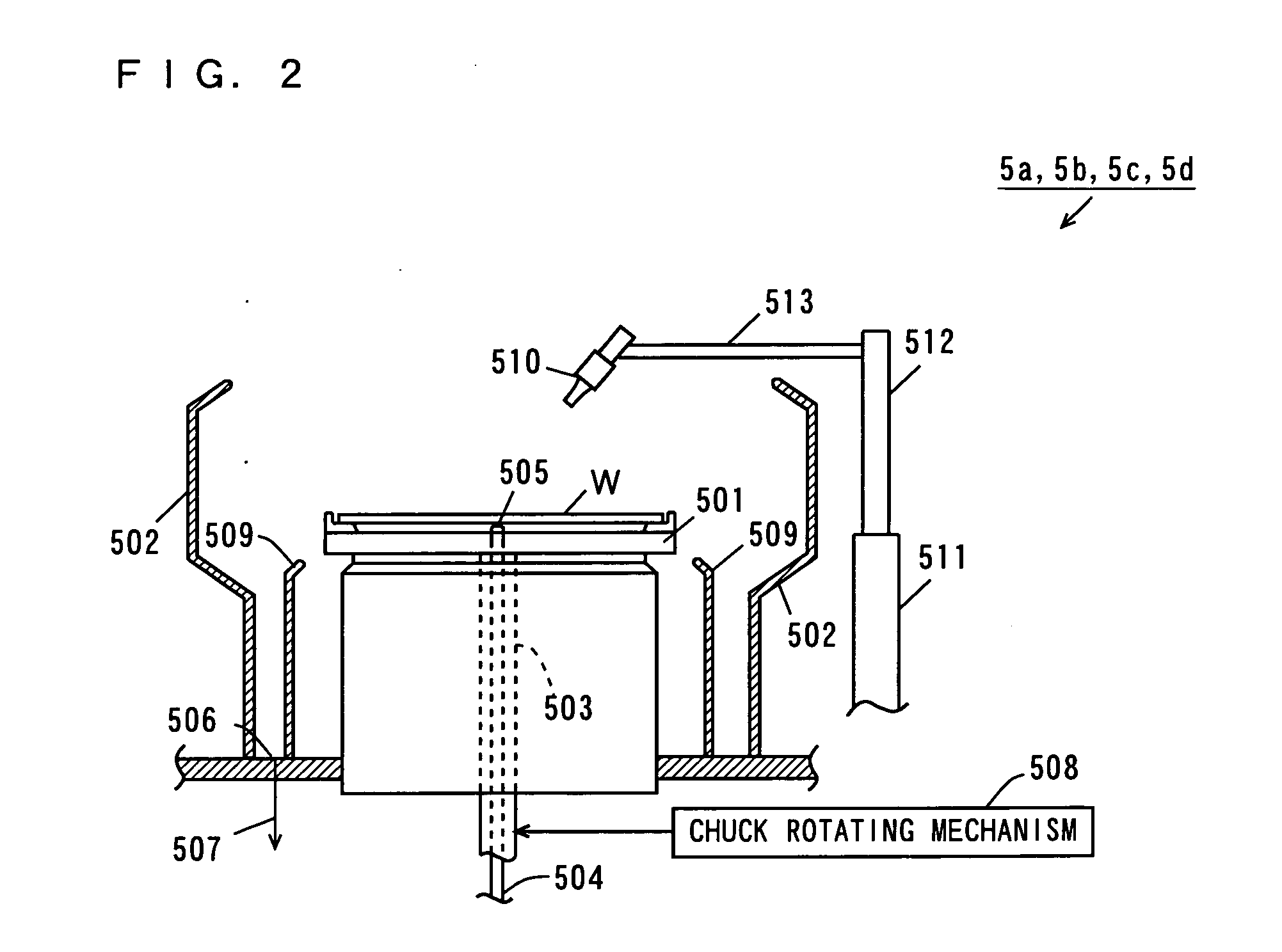
[0098] Description will be made of a substrate processing device that includes a substrate reversing device according to an embodiment of the present invention, referring to the drawings.

[0099] In the specification, a substrate refers to a semiconductor wafer, glass substrate for a liquid crystal display, glass substrate for a PDP (plasma display panel), glass substrate for a photomask, substrate for an optical disk, or the like.

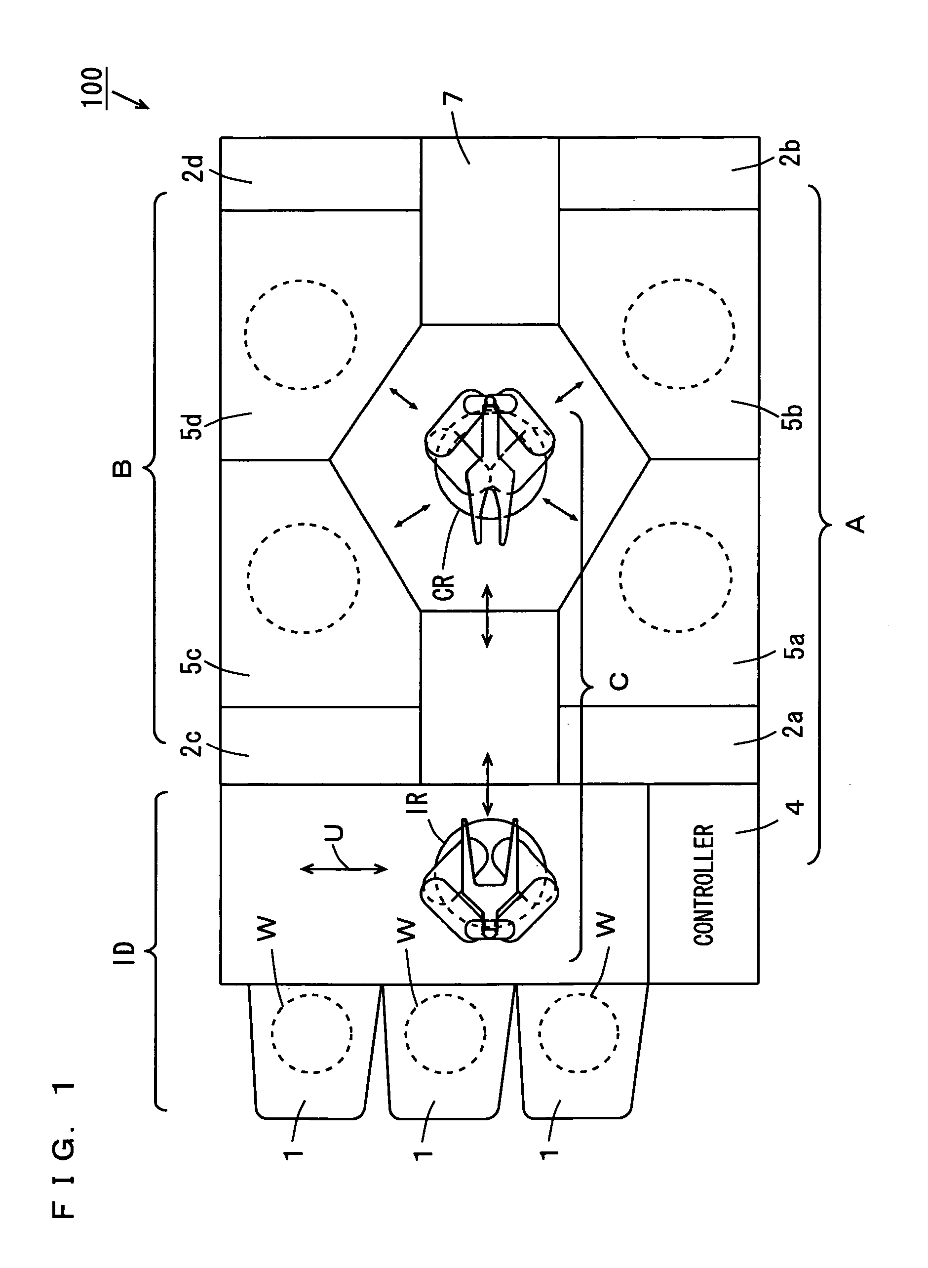
[0100]FIG. 1 is a plan view of a substrate processing device according to a first embodiment.

[0101] As shown in FIG. 1, the substrate processing device 100 has processing regions A, B, and a transporting region C between the processing regions A, B.

[0102] The processing region A includes a controller 4, fluid boxes 2a, 2b, and processing units 5a, 5b. The processing region B includes fluid boxes 2c, 2d and processing units 5c, 5d.

[0103] The fluid boxes 2a, 2b in FIG. 1, respectively, house fluid related equipment including piping, joints, valves, flow m...


PUM


Abstract

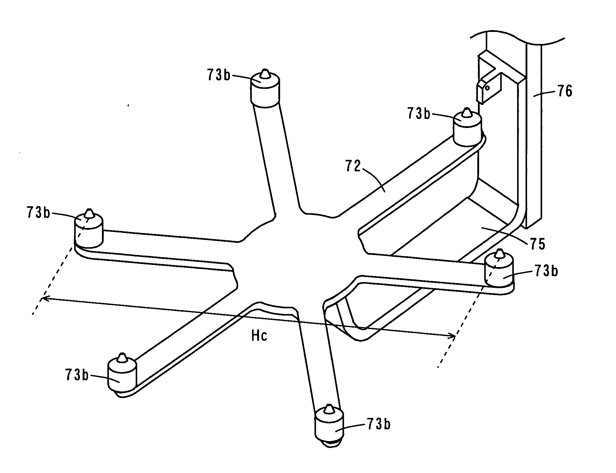
A substrate is supported on a plurality of substrate supporting pins mounted to a second movable member. Next, so as to bring the plurality of substrate supporting pins close to a plurality of substrate supporting pins mounted to a first movable member, the first movable member and second movable member are moved, respectively. After this, with the substrate being supported between the substrate supporting pins, the first movable member and the second movable member are reversed. Then, the first movable member and the second movable member are moved relative to each other such that the respective plurality of substrate supporting pins are spaced apart from one another.

Description

BACKGROUND OF THE INVENTION [0001] 1. Field of the Invention [0002] The present invention relates to a substrate reversing device and substrate reversing method for reversing a substrate, relates to a substrate transporting device and substrate transporting method for transporting a substrate, and relates to a substrate processing device and substrate processing method for applying given processes to a substrate. [0003] 2. Description of the Background Art [0004] The manufacturing process of a semiconductor device, liquid crystal display or the like involves a variety of processes applied to a substrate such as a semiconductor wafer, glass substrate or the like. The variety of processes include cleaning, resist coating, exposure, development, etching, ion implantation, resist removal, formation of interlayer insulating films, thermal treatment, and the like. [0005] In the cleaning process, contaminants such as particles attached on the substrate are removed. As patterns have recentl...

Claims


Application Information

Patent Timeline
Patent Type & Authority Applications(United States)
IPC IPC(8): B65G47/22B65G49/00H01L21/687
CPCY10S414/136H01L21/68707
Inventor HASHIMOTO, KOJI
Owner DAINIPPON SCREEN MTG CO LTD
Learn More