
Optical disc apparatus

Inactive Publication Date: 2006-03-02
SHINANO KENSHI
View PDF1 Cites 4 Cited by
  • Summary
  • Abstract
  • Description
  • Claims
  • Application Information

AI Technical Summary

Benefits of technology

[0025] The present invention was conceived in view of the problem described above and it is an object of the present invention to provide an optical disc apparatus that can carry out a data write on an optical disc with an optimal laser power when a data write is carried out at a different write speed to the speed during OPC, such as when the speed differs between the inner periphery and outer periphery of the optical disc as with ZCLV or PCAV, for example.

Problems solved by technology

However, there are cases where the characteristics of an optical disc differ between the inner periphery and the outer periphery and / or the temperature differs between the inner periphery and the outer periphery, so that even if the optimal laser power is set by an OPC carried out in the inner periphery, as the write moves toward the outer periphery of the optical disc, the laser power deviates from the optimal value for that part of the disc.
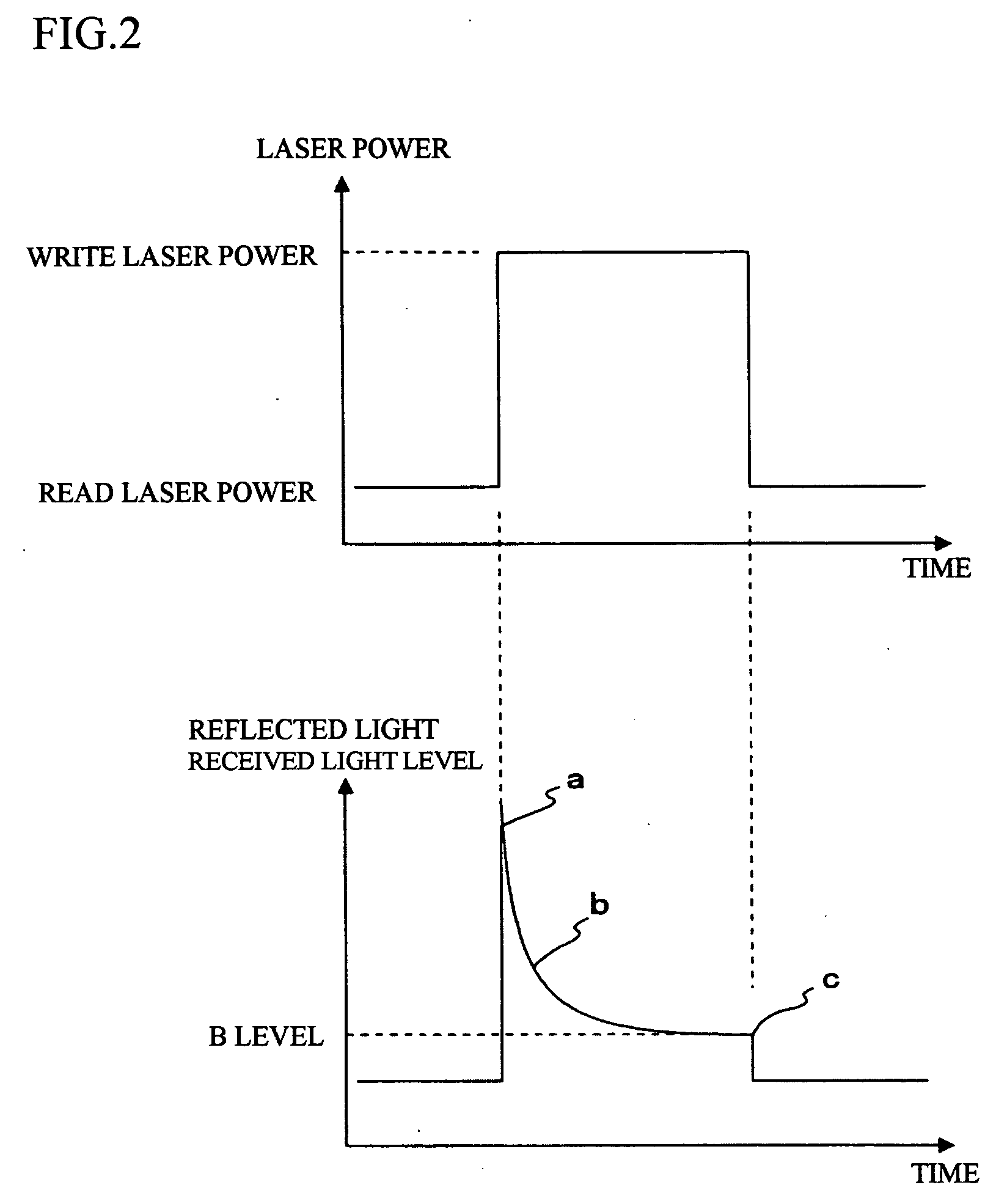
When the ROPC is executed using the B level obtained by the OPC as a reference value, if the actual data write speed is higher than (i.e., a multiple of) the speed during the OPC, there is the problem that the value of the B level obtained by the OPC will no longer be the correct value, the laser power tends to be too low, and the recording quality falls.
In this way, according to the control method for the laser power that uses conventional ROPC, in the case where the write speed changes in the outer periphery of the optical disc, even if the laser power is controlled with the B level calculated by the OPC as a reference, since the speed will change as the write moves to the outer periphery of the optical disc, the B level obtained by the OPC will deviates from the correct value, the laser power will not be controlled optimally, and the recording quality will fall.

Method used


Image

  • Optical disc apparatus
  • Optical disc apparatus
  • Optical disc apparatus

Examples


first embodiment

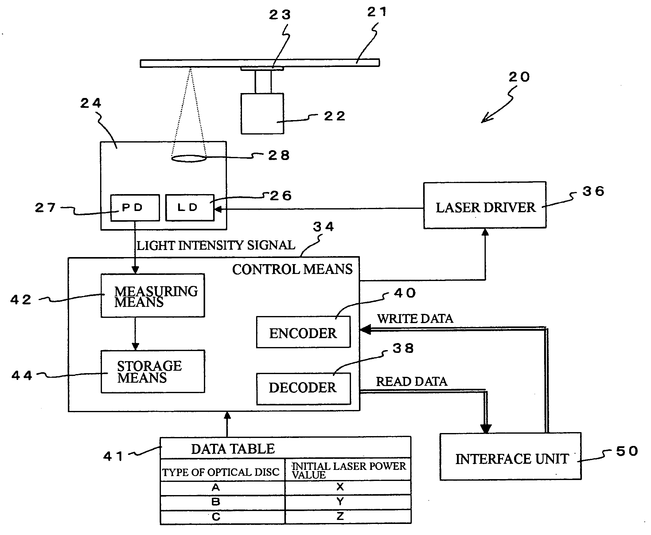
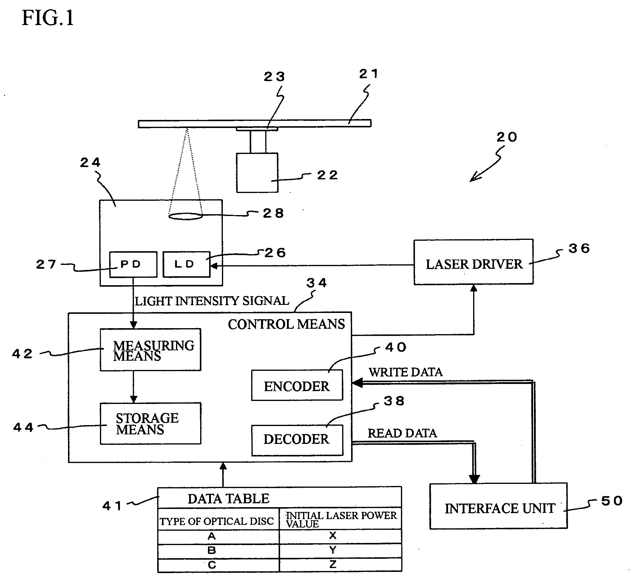
[0048] The construction of an optical disc apparatus according to the present invention will now be described with reference to FIG. 1.

[0049] An optical disc apparatus 20 includes a spindle motor 22, on which a turntable 23 for mounting an optical disc 21 is provided, and an optical pickup 24 that emits laser light on the optical disc 21 and receives laser light reflected from the optical disc 21.

[0050] The optical pickup 24 includes a laser diode (LD) 26 that outputs laser light and a photodetector (PD) 27 that is a light-receiving element. An objective lens 28 that collimates the laser light and focuses the laser light on the recording surface of the optical disc is provided inside the optical pickup 24.

[0051] In the photodetector 27, light intensity at the light receiving surface is converted to a voltage value that is inputted into a control means 34 provided outside the optical pickup 24.

[0052] The laser power of the laser light outputted by the laser diode 26 inside the op...

second embodiment

[0087] A second embodiment of an optical disc apparatus according to the present invention will now be described. FIG. 5 shows the internal construction of the second embodiment.

[0088] It should be noted that component elements that are the same as in the first embodiment described above have been assigned the same reference numerals in the drawings and description thereof has been omitted.

[0089] The control means 34 of the present embodiment carries out an operation that controls the laser power of the writing laser light so that during the ROPC operation, the B level of the laser power of the reflected light during a data write is within a predetermined range set in advance. That is, the control means 34 has a function as a measuring means 42 that measures the laser power of the reflected light from the light intensity signal and a function as a storage means 44 that stores the result of such measurement (more specifically the value of the B level of the laser power of the refle...

third embodiment

[0111] Next, a third embodiment of an optical disc apparatus according to the present invention will be described. The internal construction of the third embodiment is shown in FIG. 8.

[0112] It should be noted that component elements that are the same as in the first and second embodiments described above have been assigned the same reference numerals in the drawings and description thereof has been omitted.

[0113] The control means 34 of the present embodiment carries out an operation that controls the laser power of the writing laser light so that during the ROPC operation, the B level of the laser power of the reflected light during a data write is within a predetermined range set in advance. That is, the control means 34 has a function as a measuring means 42 that measures the laser power of the reflected light from the light intensity signal and a function as a storage means 44 that stores the result of such measurement (more specifically the value of the B level of the laser ...


PUM


Abstract

To make it possible to write data onto an optical disc with an optimal laser power even when the data is written at a different write speed to the speed during OPC, the laser power of the reflected light is measured during formation of a pit on the recording surface of the optical disc at the start of a data write, a value of the laser power of the reflected light at a time a predetermined period after a start of the formation of the pit at the start of the data write when the laser power of the reflected light has become substantially constant is set as a reference level, and during a data write in a user data area, a measuring unit is caused to continuously measure the laser power of the reflected light when pits are formed on the recording surface of the optical disc and the laser power of the laser light emitted by the laser diode onto the optical disc is controlled so that a value of the laser power of the reflected light at a time a predetermined period after the start of pit formation when the laser power has become substantially constant always matches the set reference value.

Description

BACKGROUND OF THE INVENTION [0001] 1. Field of the Invention [0002] The present invention relates to an optical disc apparatus that can write data onto an optical disc. [0003] 2. Related Art [0004] CD-R, CD-RW, DVD−R, DVD−RW, DVD+R, DVD+RW, DVD-RAM, and the like are known as examples of optical discs onto which data can be written. [0005] Before a write operation, an optical disc apparatus that is capable of writing data onto such optical discs carries out OPC (Optimum Power Control), i.e., a data writing test in a PCA (Power Control Area) that is a test writing area located at an innermost periphery of the recording surface of the optical disc, and thereby sets the power of the laser light during the data write at a suitable value. [0006] An OPC operation will now be described. [0007] The optical disc apparatus first reads optical disc identification information from the optical disc. The optical disc identification information is information relating to the optical disc and shows ...

Claims


Application Information

Patent Timeline
IPC IPC(8): G11B7/00G11B5/09
CPCG11B7/1263
Inventor NAKAMURA, HIROYUKIHANDA, YUJI
Owner SHINANO KENSHI
Learn More