Coextrusion adapter

a technology of coextrusion adapter and core, which is applied in the direction of dough shaping, manufacturing tools, applications, etc., can solve the problems of inability to profile the melt flow moving in the central conduit, inability to manufacture, and inability to affect the profile, etc., and achieve the effect of simple manufacture of the coextrusion adapter

Active Publication Date: 2006-02-23
REIFENHAUSER GMBH & CO
View PDF18 Cites 11 Cited by
  • Summary
  • Abstract
  • Description
  • Claims
  • Application Information

AI Technical Summary

Benefits of technology

[0021] In one embodiment of the coextrusion adapter in accordance with this invention there are two lateral plates, between which two conduit elements are arranged, which are spaced apart from each other and form the central conduit, wherein each conduit element is equipped with coextrusion conduits arranged laterally reversed with respect to the center axis of the central conduit and associated adjusting elements and actuating drives. Examples of such coextrusion adapters include those with one or several coextrusion conduits, for example one to three coextrusion conduits per conduit element, so that a total of six coextrusion conduits, as well as the central conduit, are provided for conducting the plastic melts, so that a maximally seven-layered composite coextrusion structure made of thermoplastic materials can be produced. It is possible to provide still fu...

Problems solved by technology

However, with this known device it is only possible to affect the profile of the melt flow supplied through the coextrusion conduit, while profiling of the melt flow moving in the central conduit, which would be desirable for achieving exact tolerances within the composite coextrusion structure, is not possible.
Although a simultaneous effect on the thickness profile of the melt flowing inside the central conduits, as well as the melt inflowing through the coextrusion conduit is possible, it is not possible to affect the selected setting from the outside without interrupting the production.
It is known from European Patent Reference EP 0 161 81...

Method used


Image

  • Coextrusion adapter
  • Coextrusion adapter
  • Coextrusion adapter

Examples


Embodiment Construction

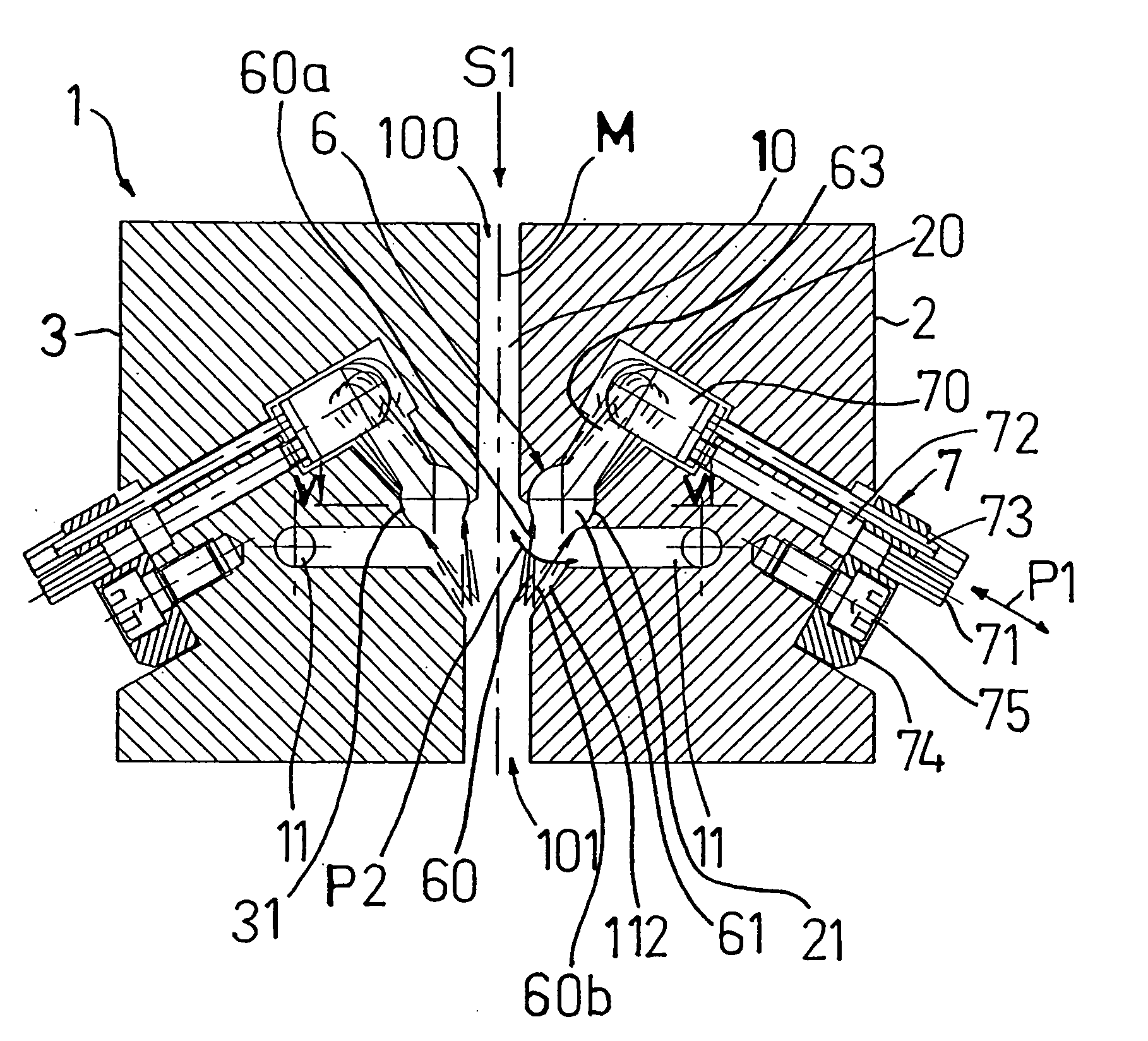
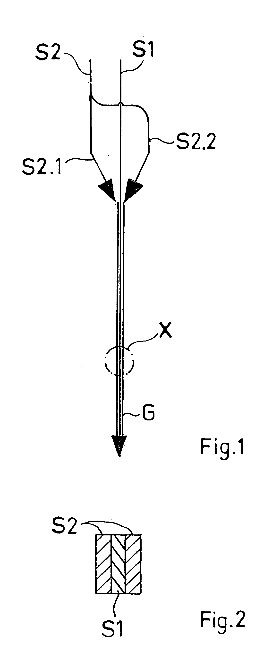
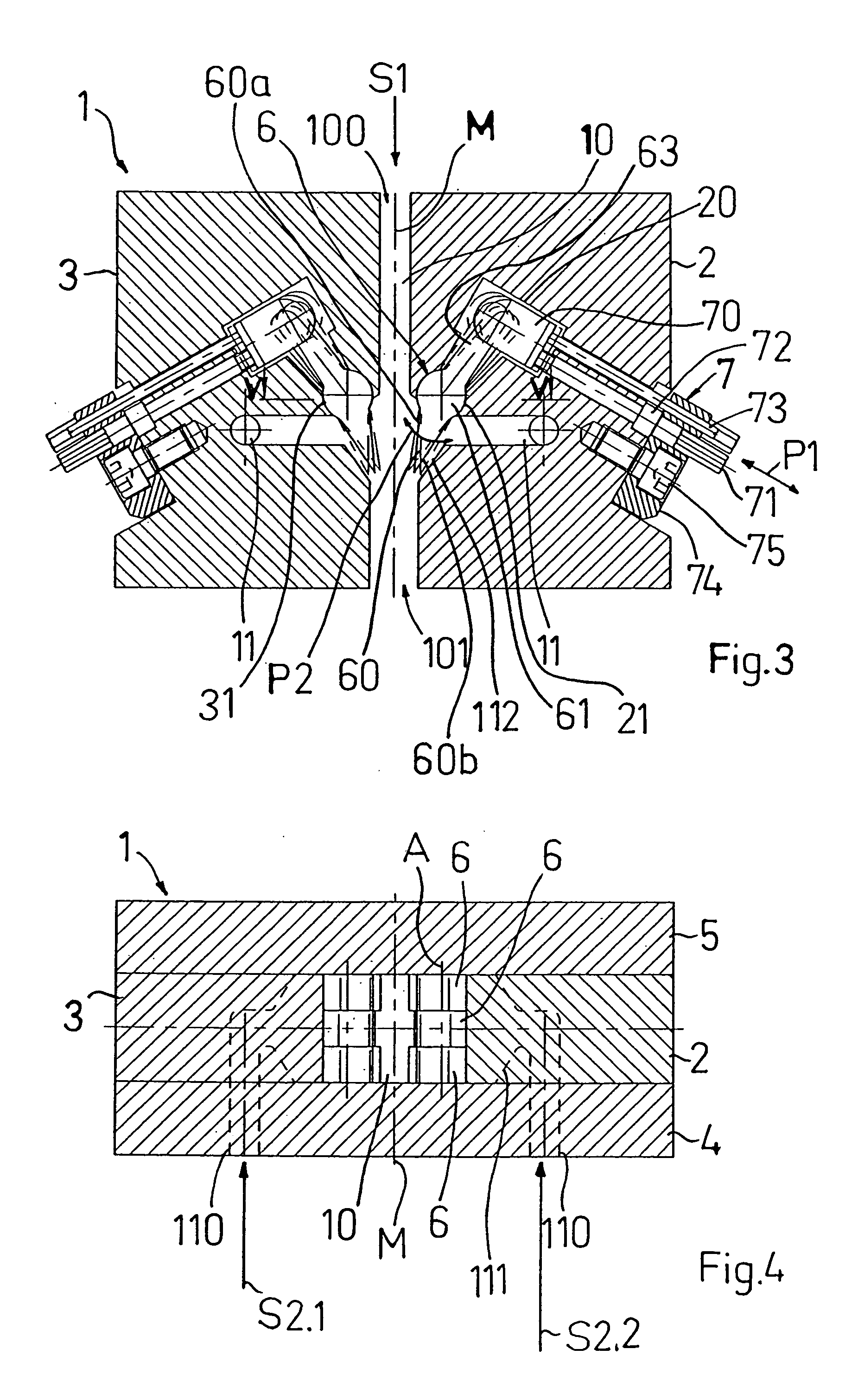
[0031] One functional principle of a coextrusion adapter for producing a multi-layer composite coextrusion structure made of a thermoplastic material is shown in FIG. 1. Different melt flows S1, S2 made of identical or different thermoplastic materials are produced by two different extruders, not shown, and are supplied under high pressure to a coextrusion adapter. In this case, the melt flow S1 is conveyed substantially in a straight line without a change of direction through a central conduit of the coextrusion adapter, which will be explained in detail later, in the direction toward the tool.

[0032] In contrast, the melt flow S2 is divided into two partial flows S2.1 and S2.2 and is conducted via coextrusion conduits on both sides to the flow S1 moving in the central conduit and are layered on top of each other to form a three-layered composite structure, such as shown in FIG. 2, wherein the melt flows S2 constitute or form the outer layers and the melt flow S1 the inner layer of...


PUM

PropertyMeasurementUnit
Widthaaaaaaaaaa
Displacementaaaaaaaaaa

Abstract

A coextrusion adapter for an extrusion installation with extruders and a tool for producing a composite coextrusion structure of thermoplastic material. The coextrusion adapter has a central conduit with an end at an inlet side for connecting an extruder and an end at an outlet side for connecting the tool. The coextrusion adapter has at least one coextrusion conduit with an inlet end and an outlet end. A second extruder can be connected to the inlet end. At an end facing the outlet end the adjusting elements have a wedge-shape adjusting section with one wedge surface facing the central conduit and another wedge surface facing the outlet end of the coextrusion conduit. The adjusting section of the adjusting elements is pivotal around an axis extending over the width of the outlet end by the actuating drives. When an increase of the inside diameter of the respective transverse section of the outlet end occurs the corresponding transverse section of the central conduit is narrowed, and vice versa.

Description

BACKGROUND OF THE INVENTION [0001] 1. Field of the Invention [0002] This invention relates to a coextrusion adapter for an extrusion installation with several extruders and a tool supplied by the extruders for producing a composite coextrusion structure of thermoplastic material, wherein the coextrusion adapter has a central conduit with an end at the inlet side for connecting an extruder and an end at the outlet side for connecting a tool, the coextrusion adapter has at least one coextrusion conduit with an inlet end and an outlet end, a further extruder can be respectively connected to the inlet end and the outlet end terminates downstream of the end at the inlet side of the central conduit in the latter, and adjusting devices are assigned to each outlet end of the at least one coextrusion conduit, which have a plurality of adjusting elements which together extend over the width of the outlet end and which can be adjusted independently of each other by actuating drives so that the...

Claims


Application Information

Patent Timeline
IPC IPC(8): B29C47/04B29C48/09B29C48/21B29C48/31B29C48/345B29C48/495B29C48/50B29C48/92
CPCB29C47/0019B29C47/0021B29C47/0057B29C47/065B29C47/0816B29C47/92B29C47/16B29C47/56B29K2105/256B29L2007/002B29C47/145B29C48/92B29C48/07B29C48/08B29C48/0018B29C48/21B29C48/2556B29C48/307B29C48/31B29C2948/92571B29C2948/926B29C2948/92628B29C2948/92904B29C48/495B29C48/09
Inventor RUBHAUSEN, ANTONSIEBIGTEROTH, PETER
Owner REIFENHAUSER GMBH & CO
Why Eureka
Try Eureka