
Solid state lighting device

a solid-state lighting and battery-powered technology, applied in the direction of electric variable regulation, process and machine control, instruments, etc., can solve the problems of inability to read the red portions of the image sensor, insufficient light for true flashlight or emergency light use, and waste of energy, so as to achieve the effect of emitted white ligh

Inactive Publication Date: 2006-02-23
TESSERA INC
View PDF0 Cites 130 Cited by
  • Summary
  • Abstract
  • Description
  • Claims
  • Application Information

AI Technical Summary

Benefits of technology

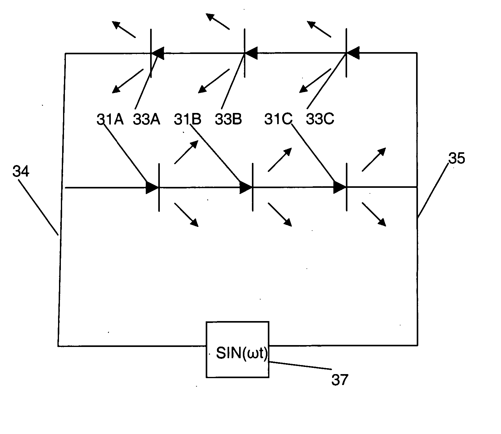
[0024] The number of individual LED elements is a matter of design choice, where, for example, a third light emitting diode, and even more diodes, may be arrayed between the first and second light emitting diodes, electrically in series therewith and bonded thereto to provide three or more light emitting diodes electrically and mechanically in series. In this case where the individual light emitting diode elements emit different primary color to thereby cause the monolithic light emitting diode array to effectively emit white light.

Problems solved by technology

This is wasteful of energy, especially stored energy, because as much as four fifths of the light is lost as ohmic heating, that is, I2R heating, and only one fifth of the energy into light.
Previously, LEDs did not produce enough light for true flashlight or emergency light use.
While white light is desired, it is not emitted by semiconductor light emitting diodes.
When the above-mentioned LEDs for emitting red light, which is reflected by the red portions because of its wavelength, is used in the LED array, the red portions in the original reflect the red light, so that the image sensor is not capable of reading the red portions.
However, in order to obtain an LED array in which different types of LEDs of different wavelengths are used to emit light beams at wavelengths at these different wavelengths in order to additively produce white light a very large number of lead wires are necessary, resulting in an LED array with complicated wiring that is expensive to manufacture.
Another problem with the new, high power LED flashlights is that blue LEDs, which are required to produce white light, have a forward voltage of 3.3 to 4.0 volts, and typically about 3.5 volts.
The design issue is that most consumer batteries have a cell voltage of 1.35 to 1.50 volt nominal.
The high voltage will damage the LED, and significantly shorten its life.
This is about 18 to 22 percent of the battery's power, and represents significant waste; especially where portability and long time between battery recharges is desired.

Method used


Image

  • Solid state lighting device
  • Solid state lighting device
  • Solid state lighting device

Examples


Embodiment Construction

[0046] The invention described herein provides a rugged and reliable, fully integrated portable lighting system for outdoor and emergency use. The system includes LEDs, a step up power supply, preferably operating in a pulse mode, at nanosecond level pulse's, and an optional rechargeable battery, and integrated battery charger.

Monolithic Light Emitting Diode Array

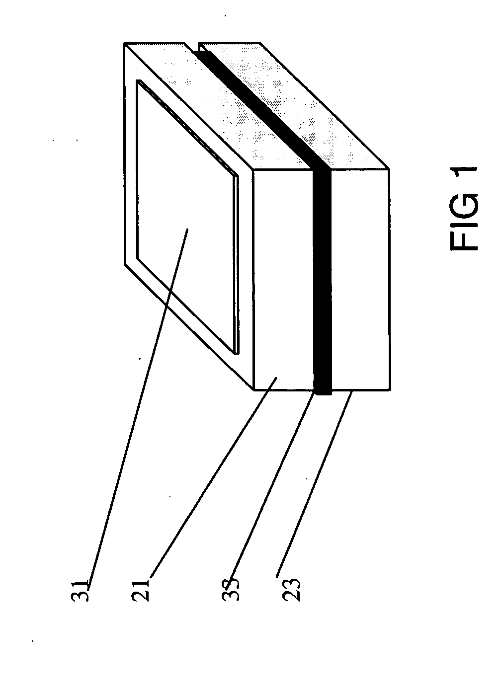
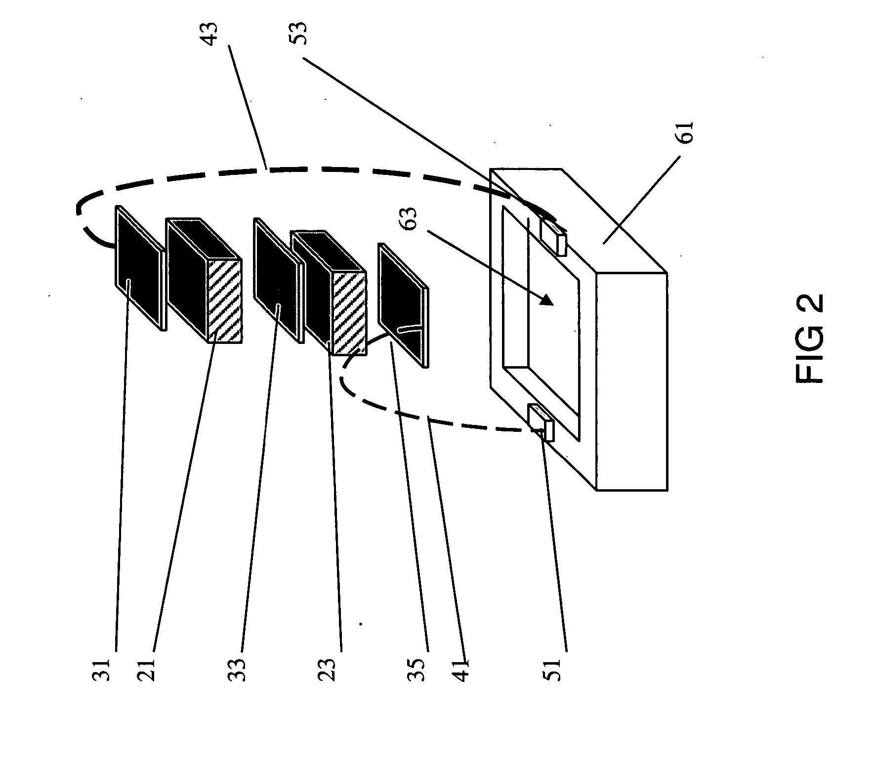
[0047] The light emitting diode series array contains a plurality of individual light emitting diode elements. The individual LED elements are electrically and mechanically in series. The array includes a first light emitting diode element having an anode region and a cathode region, and a second light emitting diode element also having an anode region and a cathode region. The individual elements are joined into a monolithic array by a conductive, rigid bond region between the cathode region of the first light emitting diode element and the anode region of the second light emitting diode element.

[0048] The array includ...


PUM


Abstract

A light assembly for use with a low voltage power source. The light assembly semiconductor photo-emitters are electrically in series with a higher forward voltage drop than the associated low voltage power supply. To provide the necessary voltage the light assembly includes a current regulated step-up DC / DC converter. The semiconductor photo-emitters that are electrically in series are in the form of a monolithic light emitting diode array with a plurality of light emitting diode elements electrically and mechanically in series with a conductive, rigid bond region between the cathode region of the first light emitting diode element and the anode region of the second light emitting diode element. The first and second light emitting diode elements may differ in band gaps to emit different colors, that are additive to a non-primary color, such as white.

Description

RELATED APPLICATION [0001] This application claims priority to the following U.S. Applications: U.S. Provisional Application No. 60 / 532,678 filed Dec. 23, 2003 and U.S. Provisional Application No. 60 / 532,340 filed Dec. 23, 2003.FIELD OF THE INVENTION [0002] Our invention relates to battery powered lighting devices, as flashlights, emergency lights, and the like, having solid state semiconductor photo-emitters, typically multiple light emitting diodes, as the lighting source. Our invention further relates to an LED (light emitting diode) series array for use, for example, in lighting devices. BACKGROUND [0003] High power light emitting diode (“LED”) portable lights, for example flashlights, emergency lights, cave lights, and the like are gaining market share. Traditional light bulbs produce light by heating a filament to its incandescence temperature. This is wasteful of energy, especially stored energy, because as much as four fifths of the light is lost as ohmic heating, that is, I...

Claims


Application Information

Patent Timeline
IPC IPC(8): G05F1/613
CPCH05B33/0803H05B33/0815H05B33/0821Y02B20/347H01L2924/13091H01L2224/16145H01L2924/01322H01L2224/48465H01L2224/48227H01L2924/3011H01L2924/12032H01L2224/48091H01L2924/00014H01L2924/00H01L2224/04042Y02B20/30H05B45/38H05B45/42
Inventor PARK, JAE M.KANG, TECK-GYU
Owner TESSERA INC
Learn More