Eureka AIR delivers breakthrough ideas for toughest innovation challenges, trusted by R&D personnel around the world.

Breaker mounting bracket

a mounting bracket and breaker technology, applied in the direction of contact mechanisms, portable drilling machines, building repairs, etc., can solve the problem of insufficient vibration absorption ability of the technique, and achieve the effect of preventing the transmission of vibration, prolonging the duration of vibration, and enhancing the operability of the working machin

Active Publication Date: 2006-02-23
TOKU PNEUMATIC TOOL MFG
View PDF4 Cites 15 Cited by
  • Summary
  • Abstract
  • Description
  • Claims
  • Application Information

AI Technical Summary

Benefits of technology

"The present invention provides a breaker mounting bracket for a working machine that can effectively absorb vibrations caused by the operation of the breaker. The bracket includes a mounting bracket body that is interposed between engaging members and a mounting bracket that is attached to the bracket body. The bracket also includes resilient bodies that come into contact with and support the breaker body. The bracket can be easily attached to the working machine and is designed to enhance the operability and reliability of the machine while reducing maintenance costs."

Problems solved by technology

Accordingly, the technique exhibits an insufficient vibration absorbing ability and hence, there has been a strong demand in this technical field for a breaker-use bracket which can sufficiently alleviate the vibrations.

Method used


Image

  • Breaker mounting bracket
  • Breaker mounting bracket
  • Breaker mounting bracket

Examples


embodiment 1

[0043] The embodiment 1 of the present invention is explained specifically in conjunction with attached drawings.

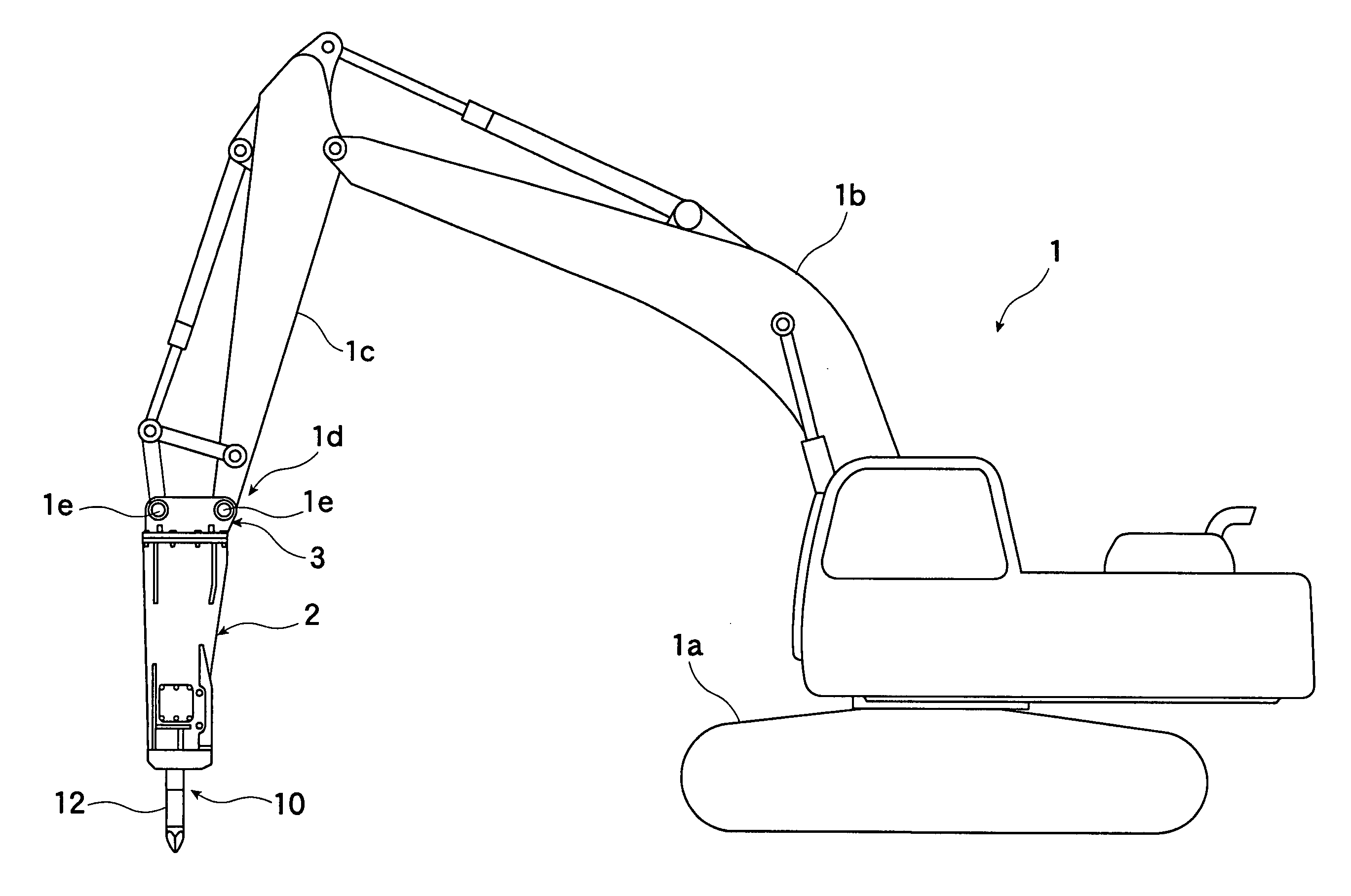
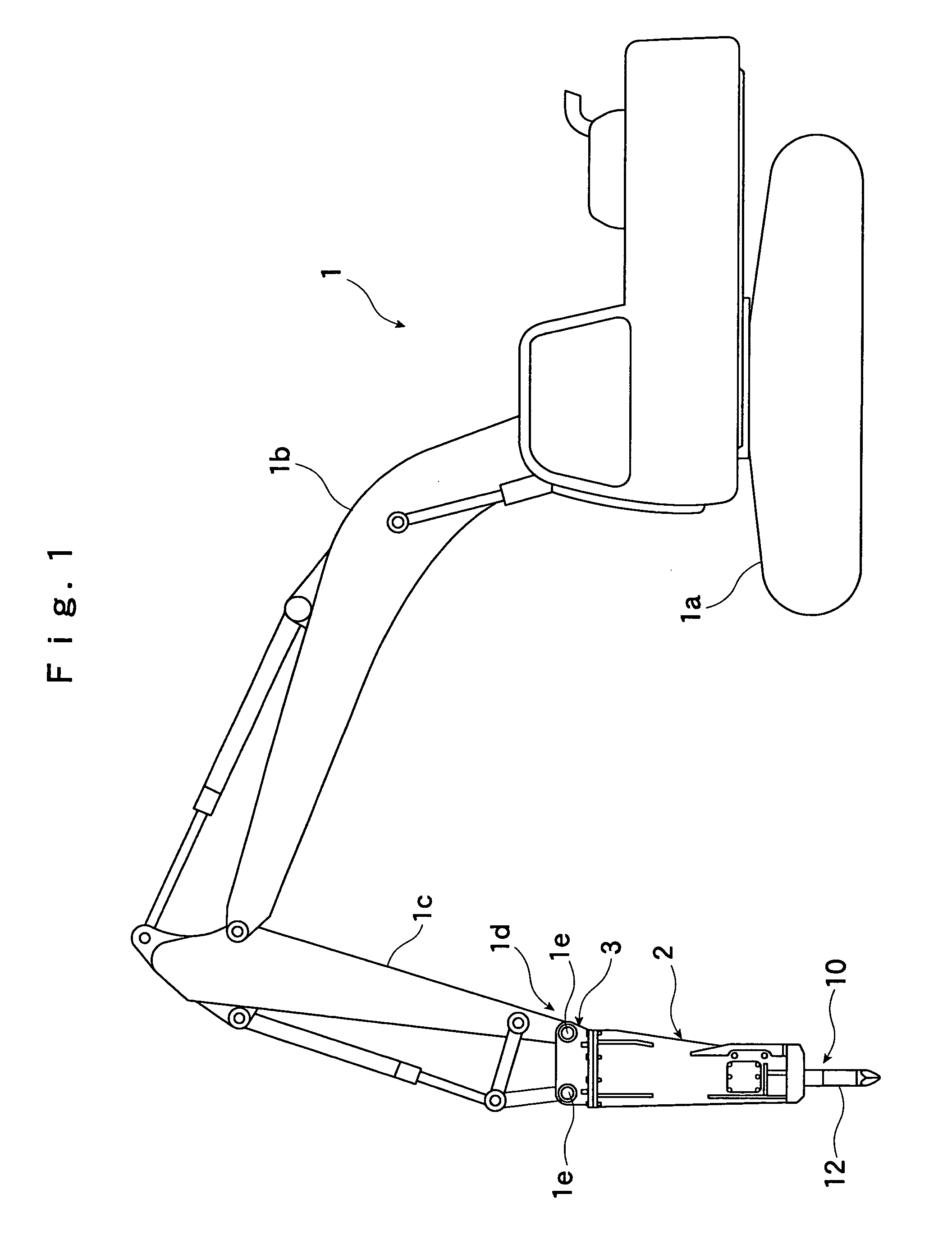
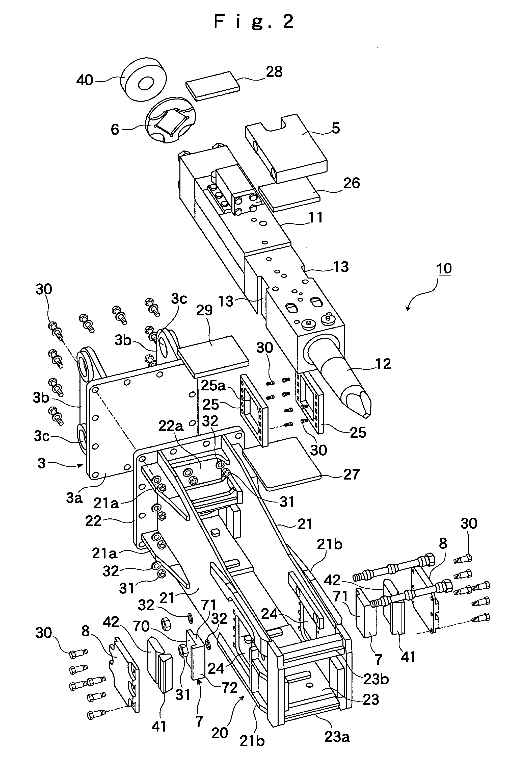
[0044]FIG. 1 is an explanatory view of a working machine which uses a breaker mounting bracket (hereinafter referred to as “bracket”) of embodiment 1, FIG. 2 is an exploded perspective view of the bracket of the embodiment 1, FIG. 3 is a perspective view of the bracket of the embodiment 1, FIG. 4 is a side view of the bracket of the embodiment 1, FIG. 5 is a bottom plan view of the bracket of the embodiment 1, FIG. 6 is a plan view with a part in cross section of the bracket of this embodiment, and FIG. 7 is an enlarged view of an essential part shown in FIG. 6.

[0045] In FIG. 1, numeral 1 indicates the working machine provided with a crawler-type traveling apparatus 1a, wherein an arm 1c is pivotally connected to the boom 1b and a breaker 10 is mounted on a distal end portion of the arm 1c by way of the bracket 2 which constitutes a gist of the embodiment 1. Numeral 1d ...

embodiment 2

[0065]FIG. 8A, FIG. 8B and FIG. 8C are a plan view, a side view and a front view of a breaker mounting bracket of the embodiment 2 respectively and FIG. 9 is an explanatory view of the support structure of a breaker body. Here, parts having the same functions as corresponding parts in the embodiment 1 are given the same symbols and the explanation thereof is omitted.

[0066] The breaker mounting bracket of the embodiment 2 includes left and right side plates 21 having an approximately rectangular shape which are arranged to face the both side surfaces of the breaker body 11 formed in a longitudinal and approximately rectangular parallelepiped shape and an end plate 22 having an approximately square shape which are arranged on proximal end sides of the side plates 21. Here, as shown in FIG. 9, the breaker mounting bracket includes a pair of left and right resilient bodies (first side-plate side resilient bodies) 101, 102 which are formed on respective inner sides of the left and right...


PUM

PropertyMeasurementUnit
pushing forceaaaaaaaaaa
supporting forceaaaaaaaaaa
durabilityaaaaaaaaaa

Abstract

The present invention provides a breaker mounting bracket a breaker mounting bracket for mounting a breaker body on a distal end of an arm of a working machine or the like. The breaker mounting bracket includes left and right side plates which are arranged to face each other in an opposed manner, an end plate which is provided between proximal end portions of both side plates and forms a connecting portion with a distal end of the arm of the working machine, and resilient bodies which come into contact with and support the breaker body and are mounted on inner sides of the left and right side plates and the end plate.

Description

BACKGROUND OF THE INVENTION [0001] 1. Field of the Invention [0002] The present invention relates to a breaker mounting bracket, and more particularly to a bracket which is served for mounting a breaker on a distal end portion of an arm of a power shovel or the like. [0003] 2. Explanation of the Related Arts [0004] Conventionally, the mounting of a breaker on a distal end of an arm of a working machine is conducted by way of a bracket. [0005] In performing a crushing operation using the breaker which is hydraulically operated, the vibrations attributed to an impact of the crushing operation are transmitted to the arm and, thereafter, are transmitted to the working machine and hence, it is difficult for an operator to smoothly manipulate the breaker. Accordingly, there has been proposed a technique which mounts a buffer device on a bracket to which the breaker is mounted (see Japanese Patent Laid-open Hei9 (1997)-155766). [0006] The buffer device disclosed in Japanese Patent Laid-ope...

Claims


Application Information

Patent Timeline
Patent Type & Authority Applications(United States)
IPC IPC(8): H01H9/20
CPCE02F3/966E04G23/082E02F3/36B25B21/02
Inventor YOSHIMURA, TADASHIHARAGUCHI, NAOFUMIJONO, KOZO
Owner TOKU PNEUMATIC TOOL MFG
Why Eureka
Eureka Blog
Learn More