Apparatus and method for forming pattern

Active Publication Date: 2006-02-16
NUFLARE TECH INC
View PDF2 Cites 23 Cited by
  • Summary
  • Abstract
  • Description
  • Claims
  • Application Information

AI Technical Summary

Benefits of technology

[0011] A first object of the present invention is to provide a pattern forming apparatus that is capable of keeping the temperature of a drawing substrate more constant when an original pattern is drawn on the drawing substrate and also capable of drawing a fine original pattern with high precision.
[0012] A second object of the present invention is to provide a pattern forming method that is capable of keeping the temperature of a drawing substrate more constant when an original pattern is drawn on the drawing substrate and also capable of drawing a fine original pattern with high precision.
[0016] According to the pattern forming apparatus and pattern forming method described above, the temperature of the glass substrate on which an original pattern is drawn can be controlled with high precision, independently of the temperature of the drawing chamber. Thus, the follow-up characteristic to the temperature variations of constant-temperature water can greatly be improved.

Problems solved by technology

It has been said that the old stepper cannot resolve an original pattern of 1 micron or less in terms of the wavelength limit of light.
However, the laser interferometer cannot sense the expansion or contraction of the glass substrate under drawing.
If, therefore, the temperature of the glass substrate changes during the drawing, a positional error occurs in the drawn original pattern.
This change is considered to be a positional error over a place for drawing the original pattern.
Since, however, the above machine parts are very heavy, their follow-up characteristic to the temperature variations of the constant-temperature water is extremely poor.
As described above, it is very difficult to keep the temperature of the glass substrate under drawing constant even though the temperature of the drawing chamber is simply regulated.

Method used


Image

  • Apparatus and method for forming pattern
  • Apparatus and method for forming pattern
  • Apparatus and method for forming pattern

Examples


first embodiment

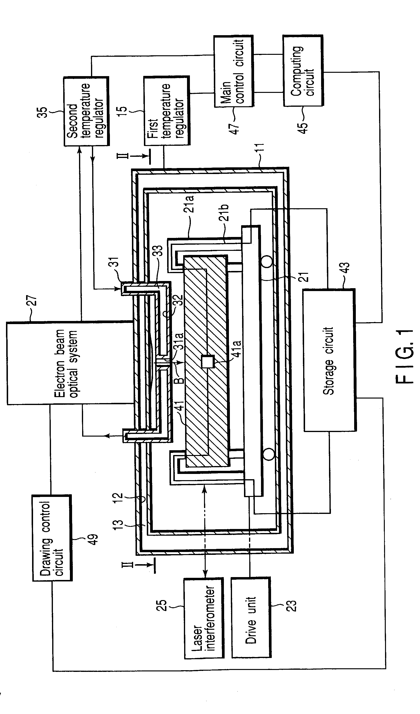
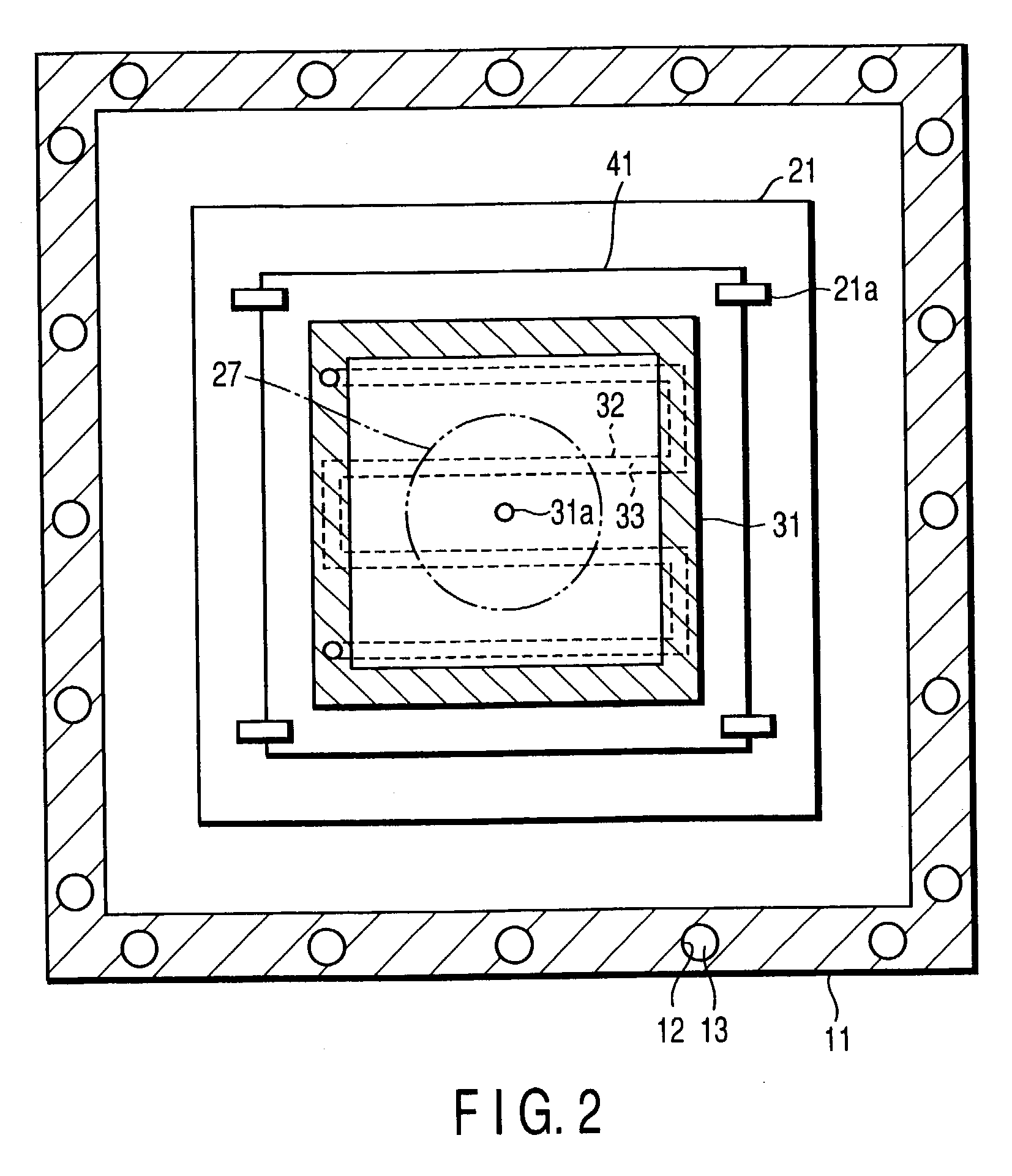
[0023]FIGS. 1 and 2 show an example of a configuration of a fine pattern forming apparatus according to a first embodiment of the present invention. In the first embodiment, a reticle manufacturing apparatus for drawing an original pattern on a glass substrate to manufacture a reticle is taken as an example of the fine pattern forming apparatus. The apparatus includes a drawing chamber 11, and the drawing chamber 11 has a circulation path 12 through which the temperature-controlled first constant-temperature water (coolant) 13 circulates in the up and down, right and left, and forward and backward walls of the drawing chamber 11. The temperature of the first constant-temperature water 13 is regulated (controlled) with high precision by a first temperature regulator 15. The first temperature regulator 15 makes up a first temperature control unit, together with a main control circuit 47 (described later).

[0024] The drawing chamber 11 contains an X-Y stage (drawing stage) 21. The X-Y ...

second embodiment

[0044]FIG. 4 shows an example of a configuration of a fine pattern forming apparatus according to a second embodiment of the present invention. The second embodiment is directed to a reticle manufacturing apparatus for drawing an original pattern on a glass substrate to manufacture a reticle. In this apparatus, the temperature of the glass substrate is measured at the time of drawing and the set temperature of a constant-temperature member is controlled based on the measurement results. As shown in FIG. 4, a thermometer (second temperature measuring device) 51 is attached on an X-Y stage 21. The thermometer 51 measures the temperature of a glass substrate 53 held on the X-Y stage 21 when an original pattern is drawn thereon. In the reticle manufacturing apparatus, the thermometer 51 attached on the X-Y stage 21 is used in place of the thermometer 41a included in the dummy mask 41 in the first embodiment and measures the temperature of the glass substrate 53 in sequence when a reticl...


PUM


Abstract

A pattern forming apparatus includes a drawing chamber having a drawing substrate on which an original pattern is drawn, a first temperature control unit having a first temperature regulator to make the temperature of the drawing chamber constant, and a constant-temperature member arranged near the drawing substrate. The pattern forming apparatus further includes a second temperature control unit having a second temperature regulator. The second temperature control unit is configured to control the set temperature of the constant-temperature member independently such that the temperature of the drawing substrate becomes substantially constant when the original pattern is drawn.

Description

CROSS-REFERENCE TO RELATED APPLICATIONS [0001] This application is based upon and claims the benefit of priority from the prior Japanese Patent Application No. 2001-398013, filed Dec. 27, 2001; the entire contents of which are incorporated herein by reference. BACKGROUND OF THE INVENTION [0002] 1. Field of the Invention [0003] The present invention relates to a pattern forming apparatus and a pattern forming method. More specifically, the invention relates to an apparatus and a method for manufacturing a reticle (or a mask) on which at least one original pattern is drawn. [0004] 2. Description of the Related Art [0005] Recently, the circuit trace widths required for semiconductor devices have become narrower and narrower as an LSI (Large Scale Integrated Circuit) increases in packing density and capacity. This type of semiconductor device is conventionally fabricated by transferring several tens of kinds of original patterns with a desired circuit pattern from a reticle aligned with...

Claims


Application Information

Patent Timeline
IPC IPC(8): G01K13/12G01K1/16G03F1/76G03F1/78G03F7/20H01J37/317H01L21/027
CPCB82Y10/00B82Y40/00G03F1/144Y10S430/143H01J37/3174H01J2237/2001H01J2237/304G03F1/36G03F1/78
Inventor HIRANO, RYOICHIIMURA, SATOSHINAKAYAMADA, NORIAKI
Owner NUFLARE TECH INC
Why Eureka
Try Eureka