Glass and laminated glass

a technology which is applied in the field of glass and laminated glass, can solve the problems of increasing the temperature of the glass of the vehicle and hindering the sensing performance of the device, and achieve the effect of keeping the temperature from increasing

Pending Publication Date: 2021-05-27
ASAHI GLASS CO LTD
View PDF0 Cites 1 Cited by
  • Summary
  • Abstract
  • Description
  • Claims
  • Application Information

AI Technical Summary

Benefits of technology

The patent describes how to make glass that is not affected by heat, which can make devices sensitive to performance. This glass helps keep the temperature down in vehicle cabins and is safe to use in vehicles.

Problems solved by technology

However, when a shielding layer is formed on glass of a vehicle, the temperature of the glass of the vehicle increases due to absorption of solar heat by the shielding layer.
There are also cases where radiant heat arising from an increase in temperature of the glass of the vehicle in turn increases the temperature of the device to the extent that the sensing performance of the device is hindered.
However, in addition to the problem of the temperature rise in the device, it is also necessary to suppress a temperature rise, within the vehicle cabin, resulting from heat inflow of solar heat from the glass.

Method used


Image

  • Glass and laminated glass
  • Glass and laminated glass
  • Glass and laminated glass

Examples


first embodiment

Third Variation of First Embodiment

[0076]The Third Variation of the First Embodiment illustrates an example that is not laminated glass. In the Third Variation of the First Embodiment, the description of the same configuration components already described in a previous embodiment may be omitted.

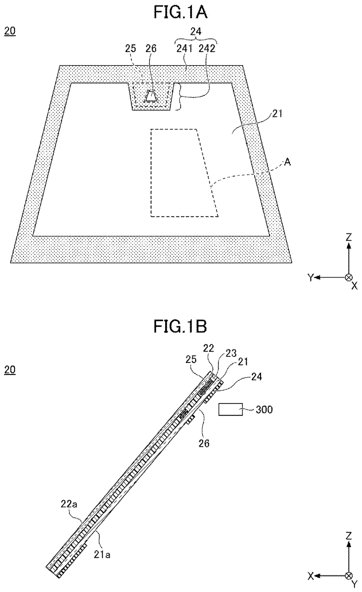
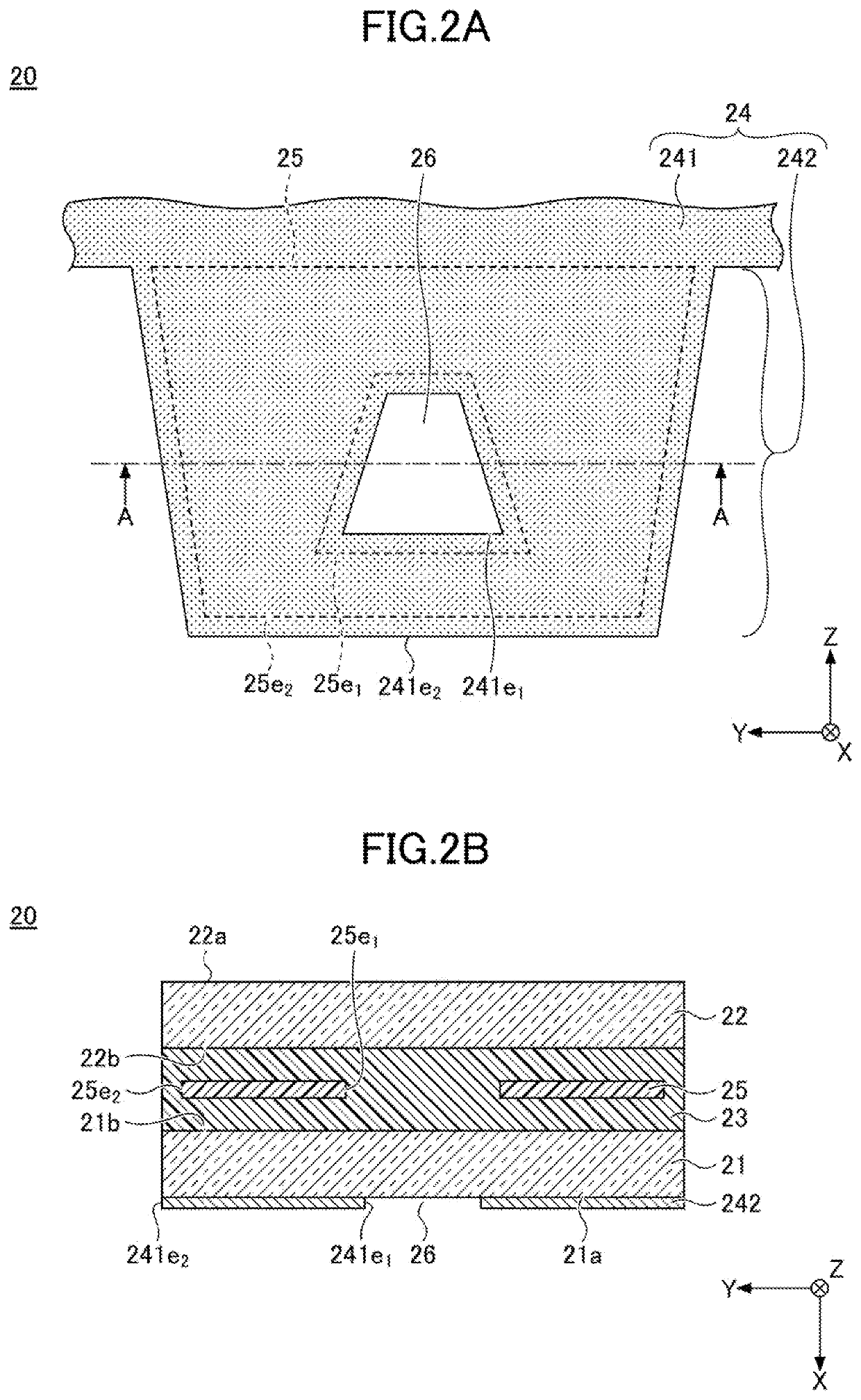
[0077]FIG. 7 is a partially enlarged cross-sectional view illustrating the vicinity of an information transmission and reception region according to a third variation of the First Embodiment and is a cross-section corresponding to FIG. 2B. In the third variation of the First Embodiment, since the partially enlarged cross-sectional view schematically illustrating an aspect of the information transmission and reception region as observed from the interior toward the exterior of the vehicle is substantially the same as FIG. 2A, no illustration is provided.

[0078]As illustrated in FIG. 7, a windshield 20E is glass for a vehicle (is not laminated glass), and includes the glass plate 22, the shieldi...

examples 1a and 1b

[0082]In Example 1A, clear glass (product name FL: manufactured by AGC Inc.) that is 300 mm in length and 300 mm in width and has a plate thickness of 2 mm was used as the glass plates 21 and 22 and polyvinyl butyral having a thickness of 0.76 mm was used as the intermediate film 23 to fabricate laminated glass equipped with a shielding layer 24 (including the protruding portion 242) made of black ceramics provided on the peripheral portion of the vehicle-interior-side surface 21a of the glass plate 21. Also, an infrared reflective layer 25 having a silver metal layer was provided in a region overlapping with the protruding portion 242, in a plan view, on the vehicle-interior-side surface 22b of the glass plate 22. Also, an infrared reflective layer (Referred to as an infrared reflective layer 35 for convenience. The infrared reflective layer 35 has a silver metal layer) with optical characteristics different from the infrared reflective layer 25 was provided in the region overlappi...

examples 2a and 2b

[0084]In Example 2A, with exception to the fact that the characteristics of the infrared reflective layer 25 were changed, the laminated glass was fabricated with substantially the same configuration as in Example 1A.

[0085]In Example 2B, with exception to the fact that the characteristics of the infrared reflective layer 25 were changed, the laminated glass was fabricated with substantially the same configuration as in Example 1B.


PUM

PropertyMeasurementUnit
Fractionaaaaaaaaaa
Fractionaaaaaaaaaa
Fractionaaaaaaaaaa

Abstract

Glass for a vehicle includes a glass plate; a test-region A demarcated in the glass plate, the test-region A being specified in JIS R3212; a shielding layer provided more outwardly than the test-region A in a plan view; an information transmission / reception region demarcated within an opening portion provided in the shielding layer, and through which a device mounted in the vehicle transmits / receives information; and an infrared reflective layer positioned peripheral to the information transmission / reception region in a plan view, the infrared reflective layer having a portion that overlaps with the shielding layer in a plan view, wherein a solar direct transmittance of the test-region A is 60% or less and a solar direct reflectance of a region in which the infrared reflective layer is provided peripheral to the information transmission / reception region is greater than a solar direct reflectance of the test-region A by at least 5%.

Description

CROSS-REFERENCE TO RELATED APPLICATIONS[0001]This application is a continuation of International Application PCT / JP2019 / 023938, filed on Jun. 17, 2019 and designated the U.S., which is based on and claims priority to Japanese Patent Application No. 2018-150612 filed on Aug. 9, 2018, with the Japan Patent Office. The entire contents of these applications are incorporated herein by reference.BACKGROUND OF THE INVENTION1. Field of the Invention[0002]The present disclosure relates to glass and laminated glass.2. Description of the Related Art[0003]In recent years, vehicles with the ability to automatically avoid collisions with vehicles travelling ahead and pedestrians are being developed. For example, for such a vehicle, a device such as a camera is mounted in the vehicle, to transmit and receive information such as road conditions via vehicle glass (e.g. windshield or the like) (see Patent Document 1, for example).[0004]Although a device such as a camera is affixed to glass of the veh...

Claims


Application Information

Patent Timeline
IPC IPC(8): C03C17/36B60J1/00B60J1/08C03C17/32C03C17/38
CPCC03C17/3644B60J1/002C03C2217/78C03C17/32C03C17/38B60J1/08B32B17/10036B32B17/10348B32B17/10357B32B17/1022B32B17/10293B32B17/10165B32B7/12B32B2605/12B32B2307/4023B32B27/308B32B27/40B32B27/306B32B27/22B32B7/022B32B2605/006B32B27/06B32B2307/732B32B2605/10B32B2307/416B32B27/36B32B2605/18B32B27/304B32B27/08B32B17/10005B32B2367/00B32B17/10192B32B17/10431C03C17/06
Inventor SADAKANE, SHUNSUKENAKAMURA, RYOTAHIRANO, AKIRA
Owner ASAHI GLASS CO LTD
Why Eureka
Try Eureka