Fan speed control circuit

a technology of speed control circuit and fan, which is applied in the direction of motor/generator/converter stopper, dynamo-electric converter control, instruments, etc., can solve the problems of destroying electronic devices, adversely affecting the operation stability of electronic devices, and unreliable and unstable operation

Inactive Publication Date: 2012-11-01
HONG FU JIN PRECISION IND (SHENZHEN) CO LTD +1
View PDF12 Cites 2 Cited by
  • Summary
  • Abstract
  • Description
  • Claims
  • Application Information

AI Technical Summary

Benefits of technology

The patent text describes a fan with a speed control circuit that can adjust the speed of the fan to prevent overheating and ensure stable operation of electronic devices. The circuit includes a power source, a resistor, a voltage stabilizing unit, a fan motor unit, a transistor, and a thermal resistor. The resistance of the thermal resistor decreases as the temperature increases, resulting in increased current flow and faster fan speed. The circuit can protect the fan motor unit against voltage spikes and other transients. The second embodiment of the circuit includes two diodes in the voltage stabilizing unit. The technical effect of this patent is to provide a fan with a speed control circuit that can adjust the fan speed to prevent overheating and ensure stable operation of electronic devices.

Problems solved by technology

Heating can adversely affect the operational stability of electronic devices.
Heat building up in electronic devices can result in unreliable and unstable operation and may even destroy the electronic device.
Generally, a fan with a one fixed speed will produce more vibration and noise than a fan capable of adjustment.

Method used


Image

  • Fan speed control circuit
  • Fan speed control circuit
  • Fan speed control circuit

Examples


Embodiment Construction

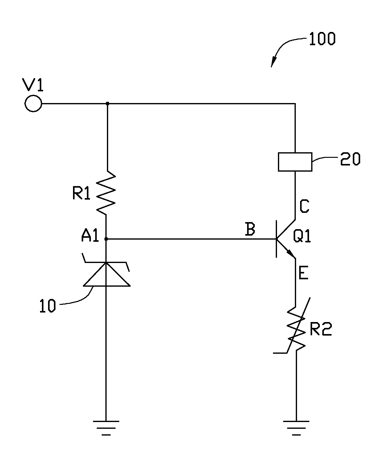
[0009]Referring to FIG. 1, a fan speed control circuit 100 in accordance with a first embodiment of the present disclosure comprises a power source V1, a resistor R1, a voltage stabilizing unit 10, a fan motor unit 20, a transistor Q1 and a thermal resistor R2.

[0010]The resistor R1 is connected between the power source V1 and the voltage stabilizing unit 10 and the voltage stabilizing unit 10 is connected to ground. A node A1 is defined between the resistor R1 and the voltage stabilizing unit 10. In this embodiment, the voltage stabilizing unit 10 is a Zener diode. The fan motor unit 20 is connected between the power source V1 and a collector of the transistor Q1. A base B of the transistor Q1 is connected to the node A1 between the resistor R1 and the voltage stabilizing unit 10. The thermal resistor R2 is connected between an emitter E of the transistor Q1 and ground. In this embodiment, the transistor Q1 is NPN-type transistor; the thermal resistor R2 is a negative temperature ch...


PUM


Abstract

A fan speed control circuit for controlling the rotation speed of a fan motor unit. The speed control circuit includes a resistor, a voltage stabilizing unit, a transistor and a thermal resistor. The resistor is connected to a power source of the fan motor unit, the voltage stabilizing unit is connected between the resistor and ground. The collector of the transistor is connected to the fan motor unit, the base is connected to a node between the resistor and the voltage stabilizing unit. The thermal resistor is connected between an emitter of the transistor and ground.

Description

BACKGROUND[0001]1. Technical Field[0002]The disclosure relates to fans, and more particularly to a fan with a speed control circuit.[0003]2. Description of Related Art[0004]Nowadays, many electronic devices generate heat during operation. Heating can adversely affect the operational stability of electronic devices. Heat building up in electronic devices can result in unreliable and unstable operation and may even destroy the electronic device. Therefore, heat should be removed timely in order to keep the temperature of the electronic devices within a safe range. Fans have been used in the electronic devices to provide forced airflows to dissipate the heat. Generally, a fan with a one fixed speed will produce more vibration and noise than a fan capable of adjustment.[0005]What is needed, therefore, is a fan to eliminate or mitigate these problems.BRIEF DESCRIPTION OF THE DRAWINGS[0006]Many aspects of the present embodiments can be better understood with reference to the following dra...

Claims


Application Information

Patent Timeline
Patent Type & Authority Applications(United States)
IPC IPC(8): G05D23/24
CPCF04D27/004Y02B30/70
Inventor HUANG, YONG-ZHAO
Owner HONG FU JIN PRECISION IND (SHENZHEN) CO LTD
Why Eureka
Try Eureka