
Suspension, magnetic head assembly, and magnetic disk drive

a technology of magnetic head slider and suspension, which is applied in the direction of magnetic recording, instruments, data recording, etc., can solve the problems of disk surface damage, vibration, and higher probability, and achieve the effect of limiting the fluctuation of the pitch attitude angle of the magnetic head slider

Active Publication Date: 2006-02-16
WESTERN DIGITAL TECH INC
View PDF16 Cites 7 Cited by
  • Summary
  • Abstract
  • Description
  • Claims
  • Application Information

AI Technical Summary

Benefits of technology

[0008] When the magnetic head slider is to be loaded on the disk, vibration can occur due to disturbance or from the loading operation itself. Should such vibration occur, a pitch attitude angle of the magnetic head slider could at times be in a minus direction (in a direction in which the air inflow end of an air bearing surface approaches more the disk surface than an air outflow end). If the magnetic head slider loads from the air inflow end, there is a stronger probability that the disk surface would be damaged. With a disk smoothed for a lower flying height in particular, a greater friction force upon contact is involved. Thus, loading of the magnetic head slider from the air inflow end makes stronger the probability of damage. There is therefore a significant challenge in assuring reliability in loading.
[0010] The mechanism disclosed in Patent Document 1 uses a member for connecting the air inflow end of the slider with the load beam. This results in a gimbal stiffness of the flexure being increased. Further, the technique disclosed in Patent Document 2 is intended for use during assembly. The technique is not aimed for loading / unloading during operation of the magnetic disk drive. It is difficult to limit the pitch attitude angle of the magnetic head slider during loading without allowing the gimbal stiffness of the flexure in an ordinary flying state to be increased.
[0011] It is therefore a feature of the present invention to provide a suspension capable of limiting fluctuations in a position of the magnetic head slider in the pitch direction.
[0012] It is another feature of the present invention to provide a magnetic head assembly capable of limiting fluctuations in the position of the magnetic head slider in the pitch direction.
[0013] It is still another feature of the present invention to provide a magnetic disk drive capable of enhancing reliability in loading and unloading of the magnetic head slider.
[0034] According to the present invention, it is possible to limit fluctuations in the pitch attitude angle of the magnetic head slider.

Problems solved by technology

When the magnetic head slider is to be loaded on the disk, vibration can occur due to disturbance or from the loading operation itself.
If the magnetic head slider loads from the air inflow end, there is a stronger probability that the disk surface would be damaged.
Thus, loading of the magnetic head slider from the air inflow end makes stronger the probability of damage.
There is therefore a significant challenge in assuring reliability in loading.
There is also another problem of degraded reliability that may be encountered when the magnetic head slider producing a large negative pressure is unloaded.
Specifically, if the limiter clearance is too wide, a small lift amount does not ensure that the magnetic head slider is unloaded at a desired position.
This results in a gimbal stiffness of the flexure being increased.
The technique is not aimed for loading / unloading during operation of the magnetic disk drive.
It is difficult to limit the pitch attitude angle of the magnetic head slider during loading without allowing the gimbal stiffness of the flexure in an ordinary flying state to be increased.

Method used


Image

  • Suspension, magnetic head assembly, and magnetic disk drive
  • Suspension, magnetic head assembly, and magnetic disk drive
  • Suspension, magnetic head assembly, and magnetic disk drive

Examples


Embodiment Construction

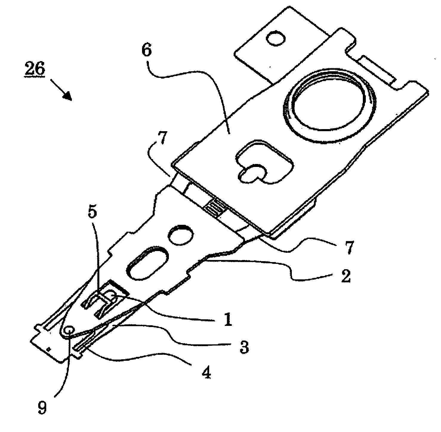
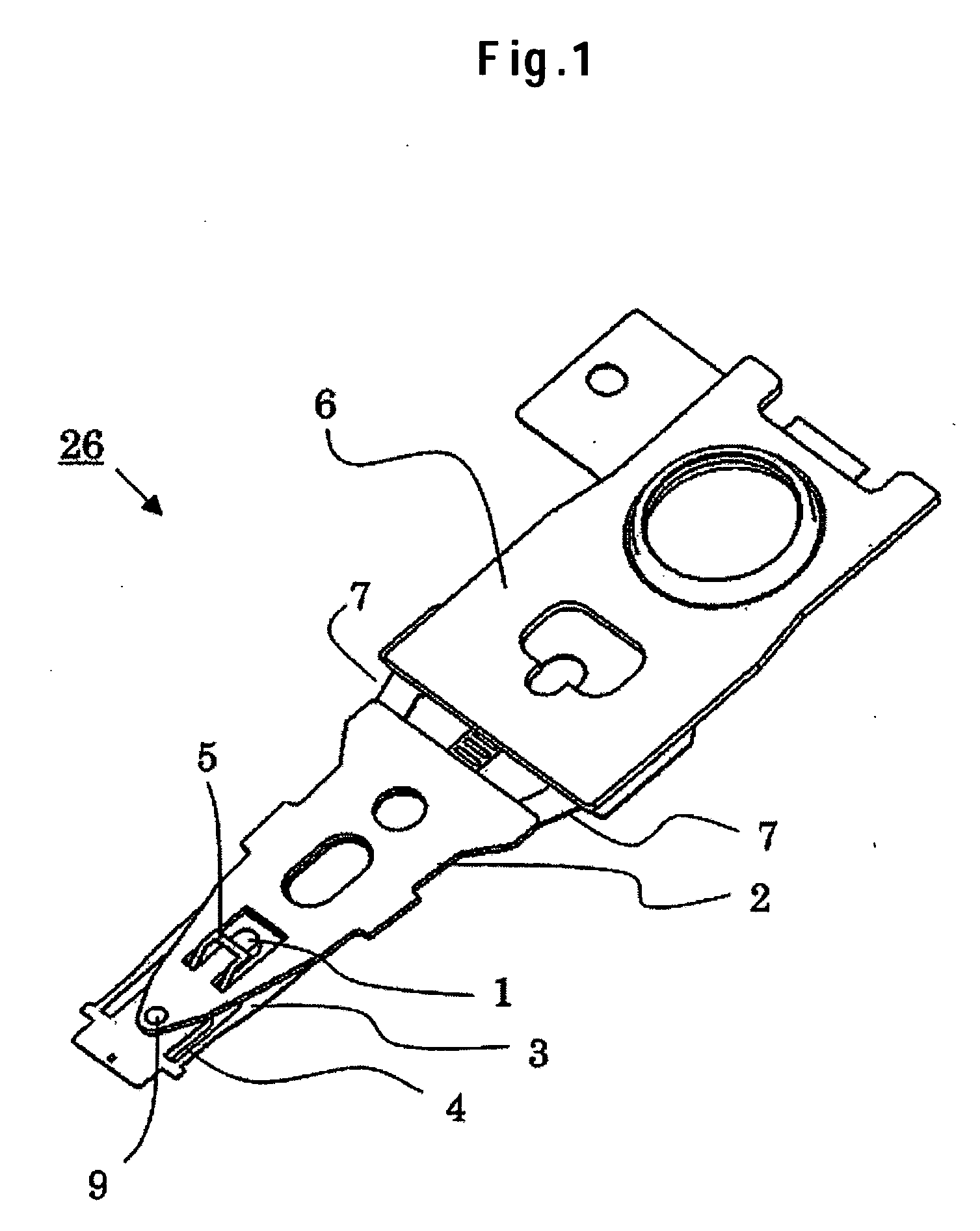
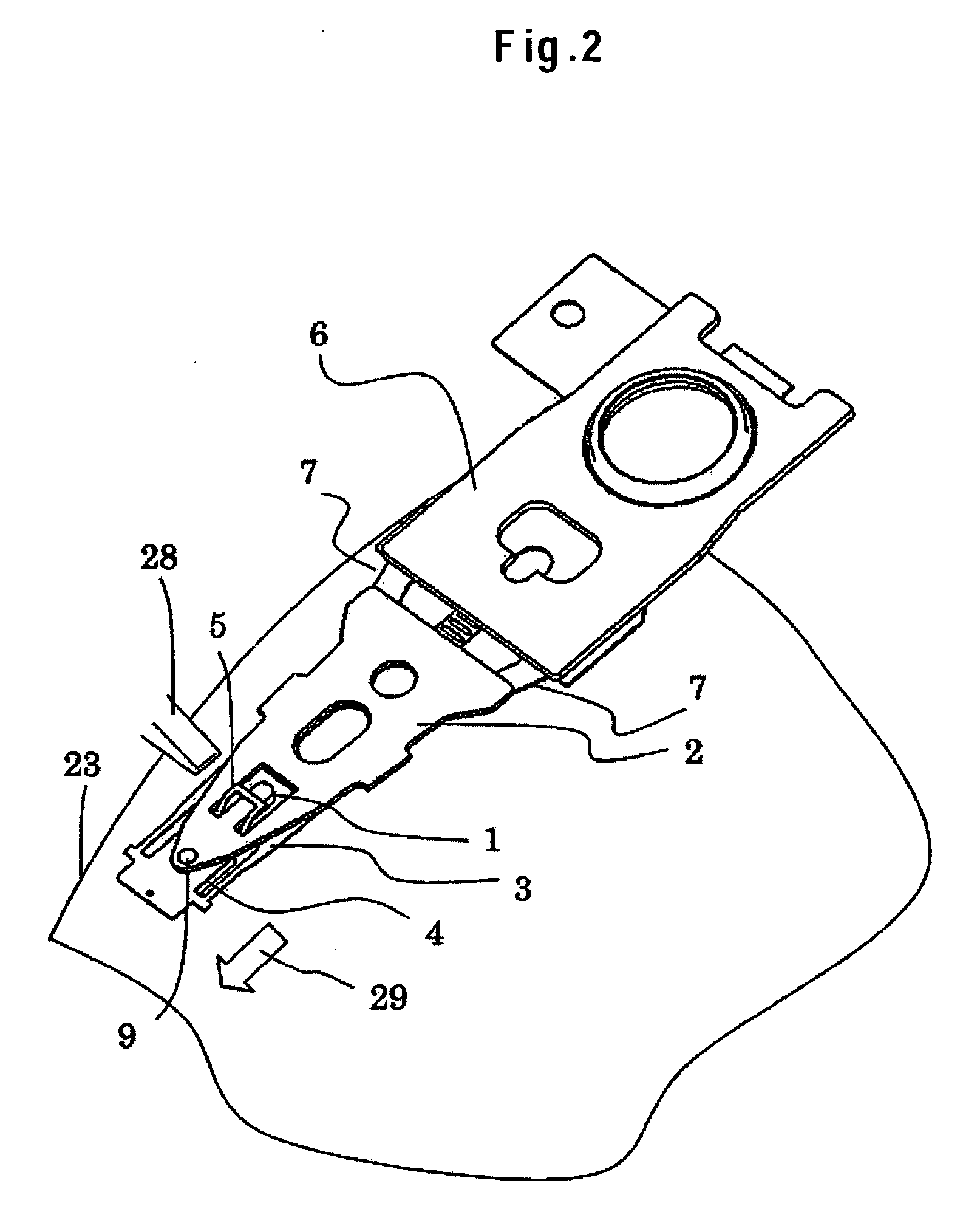
[0046]FIG. 8 shows the construction of a magnetic disk drive 20 mounted with the magnetic head assembly according to an embodiment of the present invention. A magnetic disk 23 is mounted on a rotary shaft 22 of a spindle motor secured to a base 21. The magnetic disk 23 is thus rotatably driven. A pivot 24 rotatably supports an actuator arm 25. A magnetic head assembly 26 is mounted on one end of the actuator arm 25. A coil (not shown) forming part of a voice coil motor 27 is mounted on the other end of the actuator arm 25. A magnetic head slider (not shown) is attached to a leading end of a suspension forming part of the magnetic head assembly 26. A ramp mechanism 28 is provided on the base 21 and located on an outer peripheral side of the magnetic disk 23. A slope, on which a lift tab (not shown) rides when the magnetic head slider is unloaded, is formed in the ramp mechanism 28.

[0047] When current is passed through the coil of the voice coil motor 27, rotational torque is generat...


PUM

PropertyMeasurementUnit
degree of freedomaaaaaaaaaa
thrustaaaaaaaaaa

Abstract

Embodiments of the invention limit a pitch attitude angle of a magnetic head slider during loading without allowing gimbal stiffness of a flexure in an ordinary flying state to be increased. In one embodiment, a limiter formed by part of a flexure is disposed so as to provide a clearance from a lift tab formed by part of a load beam. A limiter clearance, if the clearance between the limiter and the lift tab is so called for convenience sake, must be maintained as a physical clearance when a magnetic head slider is in an ordinary flying state. The lift tab and the limiter are disposed on a side of an air inflow end of the magnetic head slider. The limiter clearance during unloading is thereby made small so as to allow proper and positive unloading operation. In addition, the limiter clearance made small during loading allows the absolute value of a pitch attitude angle of the magnetic head slider to be limited to a small one if the pitch attitude angle tends to become negative due to disturbances or vibration from the loading operation itself.

Description

CROSS-REFERENCES TO RELATED APPLICATIONS [0001] This application claims priority from Japanese Patent Application No. JP2004-233239, filed Aug. 10, 2004, the entire disclosure of which is incorporated herein by reference. BACKGROUND OF THE INVENTION [0002] The present invention relates in general to a magnetic head suspension, a magnetic head assembly, and a magnetic disk drive, and more particularly to a mechanism for loading and unloading a magnetic head slider. [0003] When a magnetic disk drive using a load / unload (L / UL) mechanism for a magnetic head slider is operated, the magnetic head slider flies over a magnetic disk to allow information to be written and read. A suspension provides a predetermined thrust load on the magnetic head slider in a direction toward a magnetic disk surface. This thrust load balances a pressure of an air flow produced between the magnetic head slider and the magnetic disk surface. A clearance between the magnetic head slider and the magnetic disk, or...

Claims


Application Information

Patent Timeline
Patent Type & Authority Applications(United States)
IPC IPC(8): G11B5/48
CPCG11B5/486G11B5/4853
Inventor AGARI, HIROSHIGOTOU, MARUTOMOHAGIYA, SHINOBUMAEDA, NAOKINAKAMURA, SHIGEOTAKAHASHI, HARUHIDEWAKATSUKI, KOUSAKU
Owner WESTERN DIGITAL TECH INC
Learn More