
Auto-switching converter with PWM and PFM selection

a technology of auto-switching converter and pwm, which is applied in the direction of ac-dc conversion, electric variable regulation, instruments, etc., can solve the problems of reducing affecting and generating transmission losses and switching losses of electronic products. to achieve the effect of enhancing the efficiency of electronic products

Inactive Publication Date: 2006-02-16
NIKO SEMICON
View PDF6 Cites 34 Cited by
  • Summary
  • Abstract
  • Description
  • Claims
  • Application Information

AI Technical Summary

Benefits of technology

"The present invention is about improving the efficiency of electronic products by automatically switching between PWM and PFM switching modes based on the load. An auto PWM / PFM controller is used that receives a starting-enabling signal, a reference voltage signal, an error signal, and a reset signal. The controller then outputs a selection signal to either a PWM controller or a PFM controller, which in turn sends a control signal to a power switch unit to supply DC power to the load. The technical effect of this invention is to optimize the use of power and improve the efficiency of electronic products."

Problems solved by technology

The PWM switching technique is used to control the switching action of power switches to supply power to an electronic product when the electronic product is working under a full or heavy load, and at this time, the electronic product produces a transmitting loss and a switching loss.
Therefore, the efficiency of the electronic product is reduced when working under a low load with the PWM switching scheme.

Method used


Image

  • Auto-switching converter with PWM and PFM selection
  • Auto-switching converter with PWM and PFM selection
  • Auto-switching converter with PWM and PFM selection

Examples


Embodiment Construction

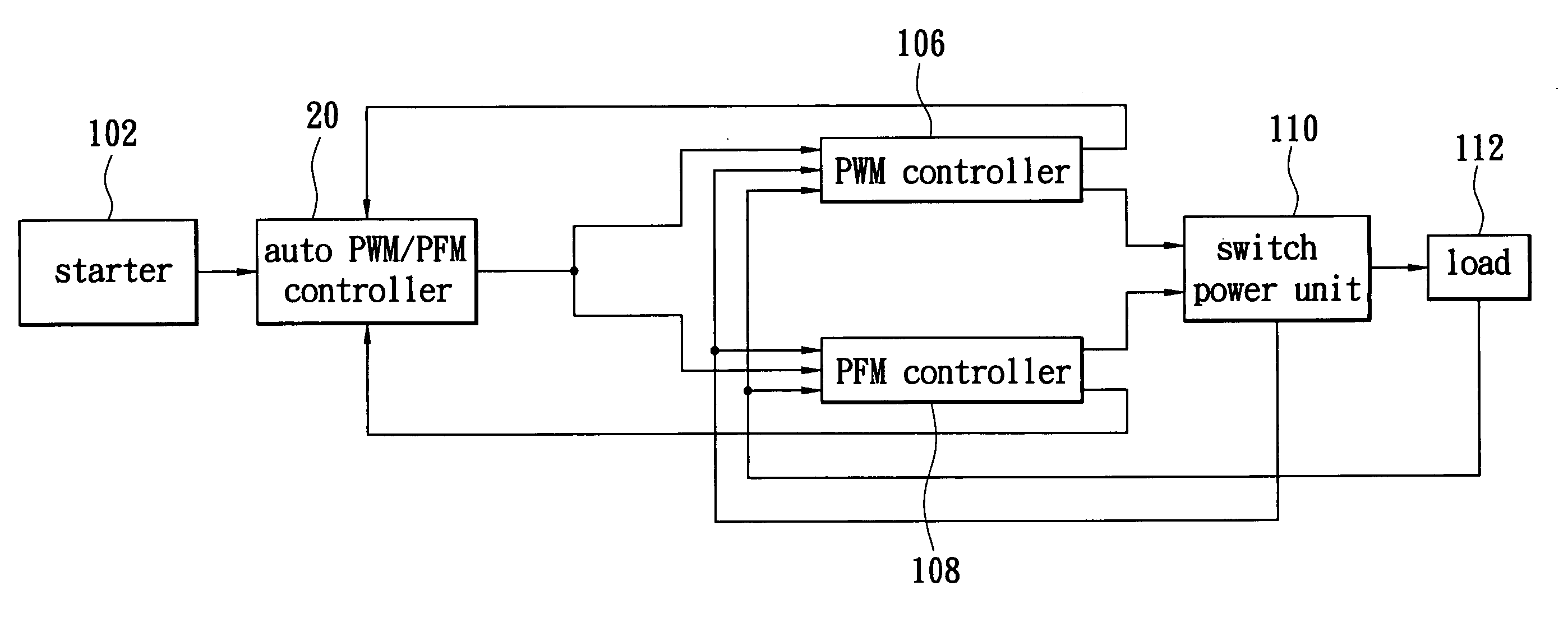
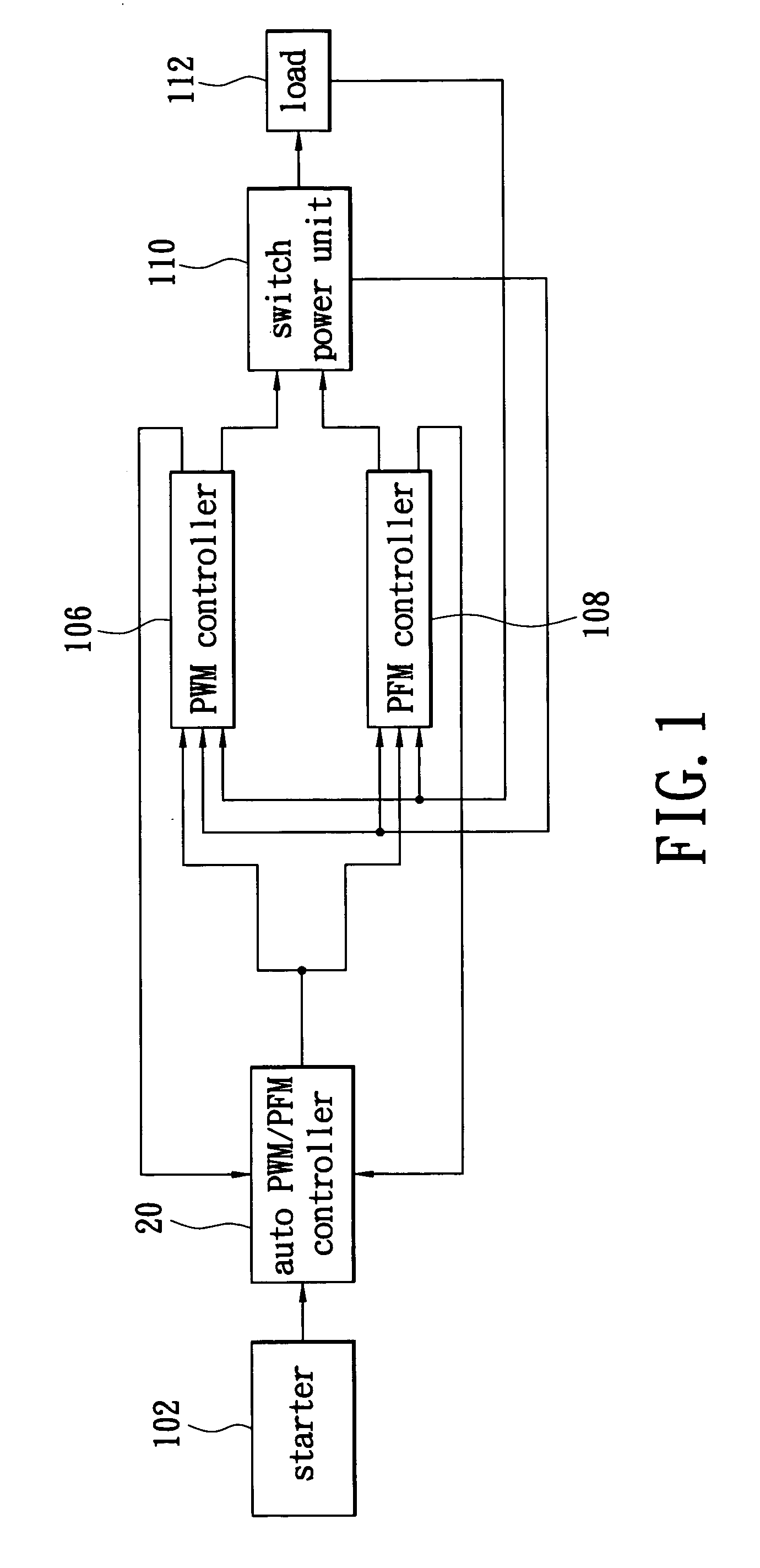
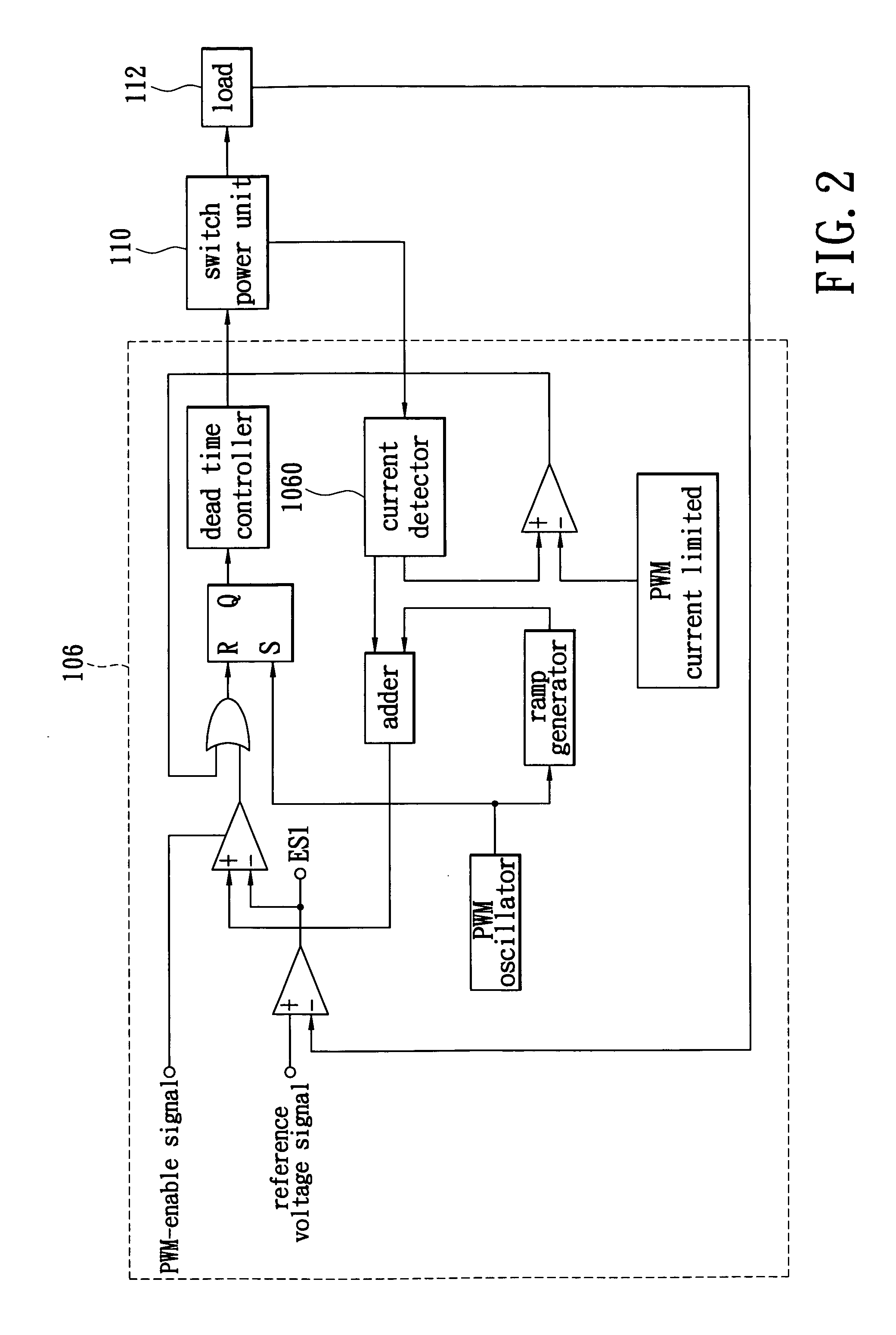
[0015]FIG. 1 is a schematic circuit diagram of the present invention. The present invention uses an auto PWM / PFM controller 20 to connect to a starter 102, a PWM controller 106 and a PFM controller 108. The starter 102 transmits a starting-enabling signal to the auto PWM / PFM controller 20 for enabling the auto PWM / PFM controller 20. After enabling the auto PWM / PFM controller 20, the PWM controller 106 and the PFM controller 108 transmits a feedback signal to the auto PWM / PFM controller 20, respectively, for driving the auto PWM / PFM controller 20 to output a selection signal. The auto PWM / PFM controller 20 transmits the selection signal to enable either the PWM controller 106 or the PFM controller 108. Moreover, the enabled controller transmits a control signal to a power switch unit 110, which is connected to the PWM controller 106 and the PFM controller 108. The control signal drives the power switch unit 110 to switch to supplying a DC power to a load 112, which is connected to th...


PUM


Abstract

An auto-switching converter with PWM and PFM selection supplies a boosted DC power to a load through a power switch unit. A starter outputs a starting-enabling signal. An auto PWM / PFM controller is connected to the starter for outputting a selection signal. A controller and a PFM controller are connected to the auto PWM / PFM controller, the power switch unit and the load for transmitting a PWM control signal and a PFM control signal to the power switch unit, respectively, for controlling the switching action of the power switch unit.

Description

BACKGROUND OF THE INVENTION [0001] 1. Field of the Invention [0002] The present invention relates to an auto-switching converter with PWM and PFM selection, and more specifically to a converter used -to auto-switch either a PWM (pulse width modulation) or a PFM (pulse frequency modulation) module to perform DC to DC or AC to DC in response to variation of the load. [0003] 2. Description of the Related Art [0004] Electronic products are used universally, and power supply for electronic products is very important. At present, power for electronic products is universally supplied with a switching technique, and PWM and PFM are two kinds of switching schemes. [0005] The PWM switching technique is used to control the switching action of power switches to supply power to an electronic product when the electronic product is working under a full or heavy load, and at this time, the electronic product produces a transmitting loss and a switching loss. Moreover, when the electronic product is...

Claims


Application Information

Patent Timeline
Patent Type & Authority Applications(United States)
IPC IPC(8): G05F1/40
CPCY10S323/901H02M3/156
Inventor WU, CHUNG CHENG
Owner NIKO SEMICON
Learn More