
Elastomeric seal assembly having auxiliary annular seal components

a technology of annular seals and elastomeric seals, which is applied in the direction of engine components, mechanical equipment, cutting machines, etc., can solve the problems of increasing the deflection and wear of seal components, increasing the amount of time required to make a round trip for replacing a bit, and essentially losing the amount of drilling operations

Inactive Publication Date: 2006-02-16
SMITH INT INC
View PDF71 Cites 42 Cited by
  • Summary
  • Abstract
  • Description
  • Claims
  • Application Information

AI Technical Summary

Benefits of technology

The patent describes a seal assembly and drill bit with a sealing seal and an auxiliary seal member that work together to create a dynamic and static seal. The auxiliary seal member can be shaped to match the static sealing surface and can be made of different materials to achieve different properties. The seal assembly and bit also have a lubricant reservoir to help with lubrication. Overall, the invention improves the sealing performance of drill bits and reduces the likelihood of sealing failures.

Problems solved by technology

When cuttings are conveyed into the seal gland, they tend to adhere to the gland and / or seal component surfaces, and may cause undesirable increased deflection and wear to the seal components.
Moreover, the cuttings can accelerate abrasive wear of all seal components and of the bearing surfaces.
The amount of time required to make a round trip for replacing a bit is essentially lost from drilling operations.
As is thus obvious, this process, known as a “trip” of the drill string, requires considerable time, effort and expense.
Importantly, the seals must function for substantial periods under extremely harsh downhole conditions.
One cause of bit failure arises from the severe wear or damage that may occur to the bearings on which the cone cutters are mounted.
These bearings can be friction bearings (also referred to as journal bearings) or roller type bearings, and are typically subjected to high drilling loads, high hydrostatic pressures, and high temperatures.
During operation, localized temperature increases, caused by inadequate lubrication or abrasive penetration, may result in the ID seal surface becoming static by sticking to the journal shaft, and the OD seal surface then becoming dynamic.
When rotation occurs at the OD seal surface, which is usually formed from a relatively soft elastomer and has a relatively poor wear resistance, the OD seal surface experiences severe wear, and the seal may fail after a short time.
The service life of bits equipped with such elastomeric seals is generally limited by the ability of the seal material to withstand the different temperature and pressure conditions at each dynamic and static seal surface.
Where such seal components experience damage, the lubricant is able to escape, and cutting-laden drilling fluid is allowed to enter the seal gland causing still further deterioration and damage to the seal components.
Eventually, enough cuttings may pass into the journal gap and / or enough lubricant may be lost from the bearing area such that rotation of the cone cutter is impeded and drilling dynamics are changed, eventually requiring the bit to be removed from the borehole.
For example, if the gland is too large or the seal too small, the appropriate squeeze on the seal will not be provided and, in turn, the desired seal footprint and sealing pressure on the journal surface will be lacking.
In such instances, the seal will not perform its intended function and the bit may prematurely fail.
Likewise, if the seal is too large or the gland too small, an excessive sealing pressure and footprint may result, causing excessive heating and thermal failure of the seal.
Once again, this can lead to bit failure.
The requirement for the elastomeric seal to provide the precise contact pressure and footprint against the adjacent sealing surfaces creates difficulties for bit manufacturers.
This, in turn, may require a difficult-to-machine seal gland be formed in order to retain the non-conventional seal.
In this instance, manufacturing the bit could be extremely expensive or even cost prohibitive, requiring that a compromise be made by the bit designer in which the bit design would surrender certain features desirable for good seal performance in order to ease manufacturing difficulties.
Even for the same size bit, the manufacturer may be required to machine many types of seal glands for the same size of seals and bits, resulting in an increase in manufacturing cost.
In turn, this leads to the manufacturer being required to make and inventory a large number of seals of substantially similar construction and materials, but of a myriad of cross- sectional areas.
The manufacturing is further complicated and made more expensive by the requirement that this large number of differently-sized seal rings be molded and, once completed, retained in inventory.

Method used


Image

  • Elastomeric seal assembly having auxiliary annular seal components
  • Elastomeric seal assembly having auxiliary annular seal components
  • Elastomeric seal assembly having auxiliary annular seal components

Examples


Embodiment Construction

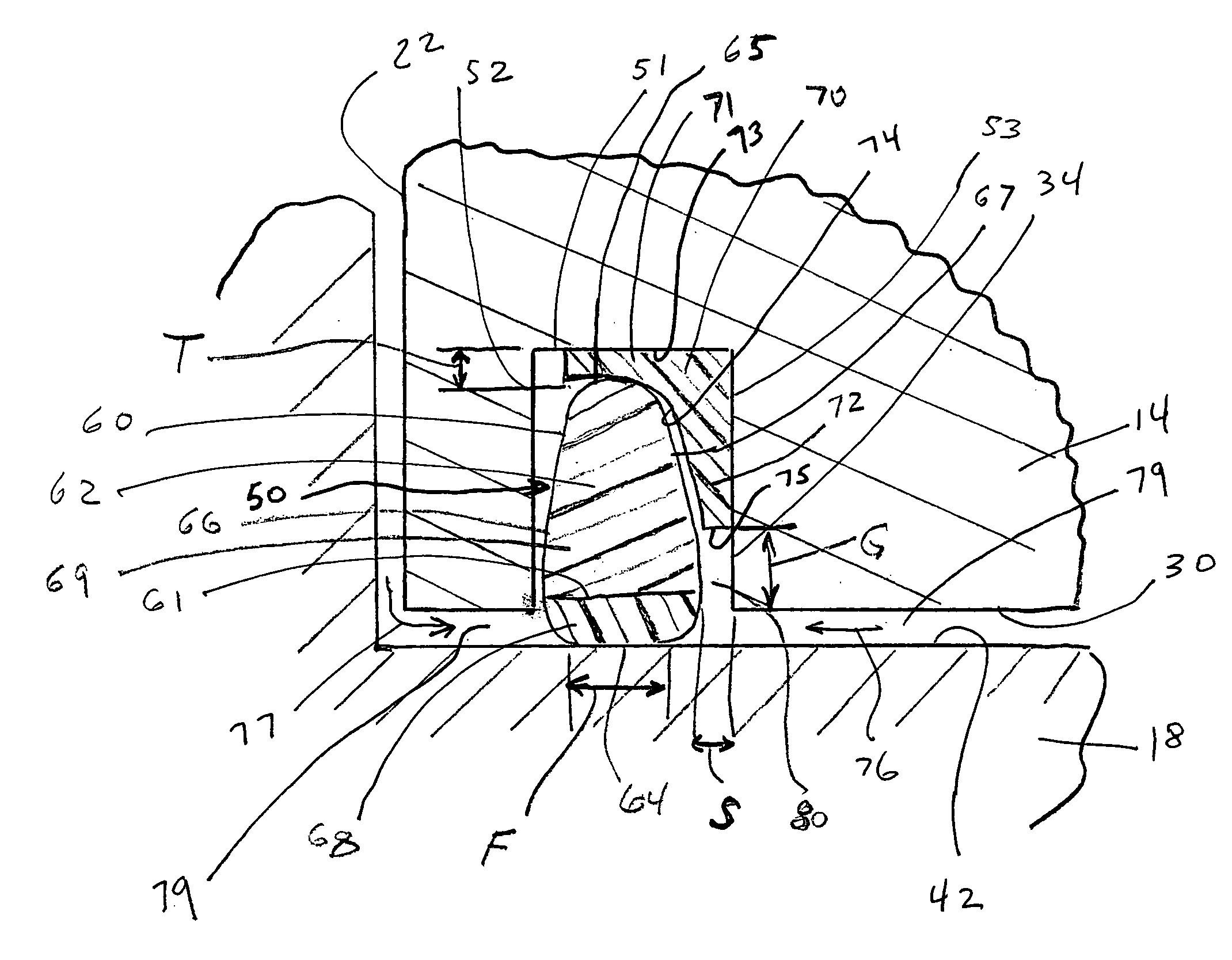
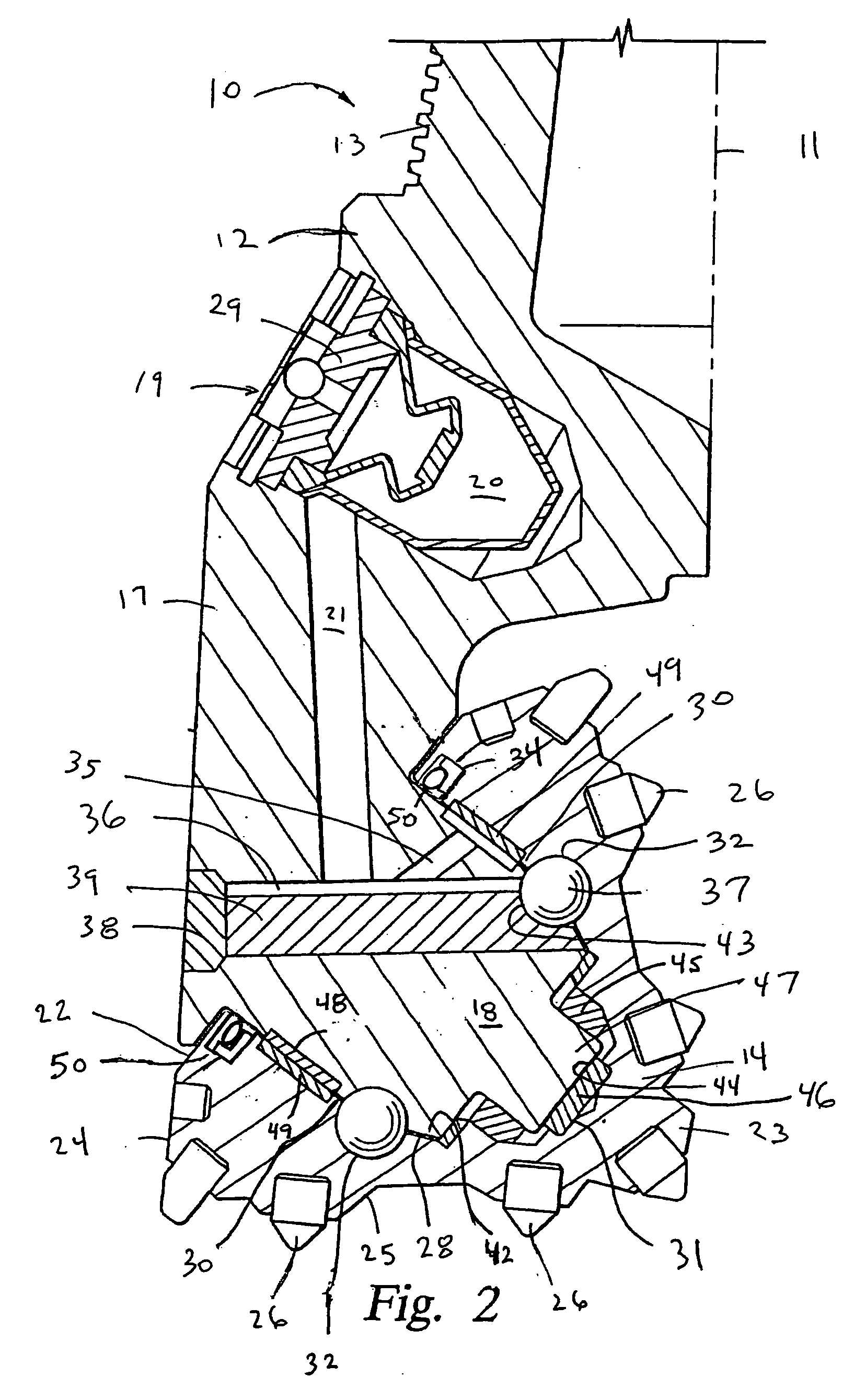
[0022] In one embodiment, a seal assembly for a drill bit includes an elastomeric annular sealing seal and an auxiliary annular seal member engaging the sealing seal, the sealing seal and the auxiliary seal member being disposed in a seal gland of the bit and collectively establishing a dynamic and a static seal.

[0023] In another embodiment, a drill bit includes a cone cutter rotatably mounted on a journal shaft, an elastomeric sealing seal disposed about the journal shaft in a seal gland, where the sealing seal includes a dynamic sealing surface for dynamically engaging the journal shaft and a static seal surface opposite from the dynamic sealing surface. The drill bit further includes at least one auxiliary annular seal member disposed about the journal shaft in the seal gland and engaging both the seal gland and the static surface of the sealing seal.

[0024] The drill bit and seal assemblies may include one or more auxiliary annular seal members in the seal gland engaging the st...


PUM


Abstract

A drill bit and seal assembly therefor include a seal gland, an elastomeric sealing seal disposed in the seal gland and having a dynamic sealing surface and a static sealing surface, and at least one auxiliary elastomeric annular seal member disposed between the static sealing surface of the sealing seal and the seal gland. The auxiliary annular seal member serves to prevent relative movement of the sealing seal relative to the surfaces of the seal gland and to permit sealing seals of various cross-sections and shapes to adapt to and function with a conventionally sized and shaped gland. The auxiliary annular seal member is sized and configured and its material properties selected so as to impart the appropriate squeeze to the sealing seal to provide the desired contact pressure and footprint. Choice of the appropriate auxiliary seal member may permit the same sized seal to be employed in seal glands of differing sizes.

Description

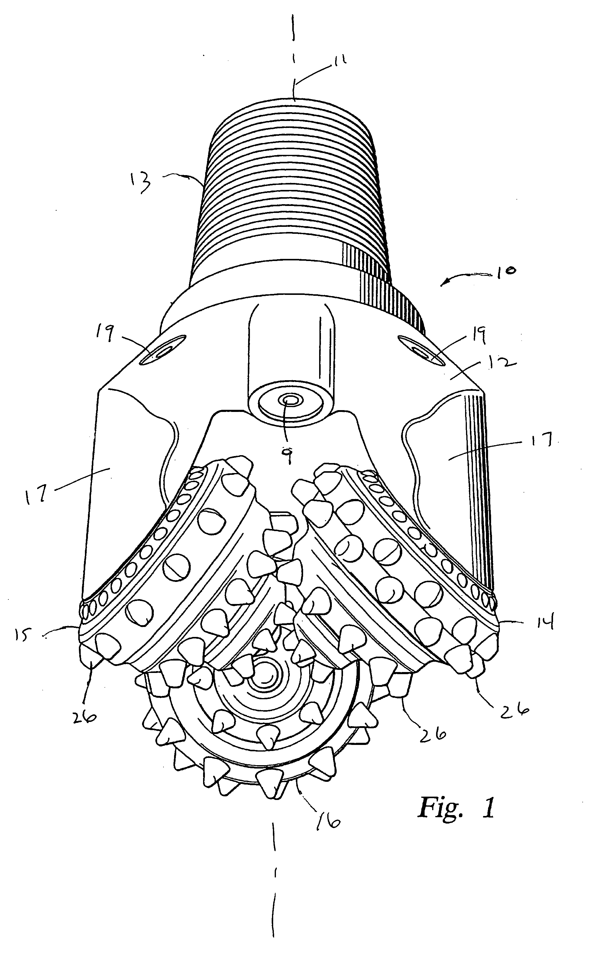
CROSS-REFERENCE TO RELATED APPLICATIONS [0001] Not Applicable. STATEMENT REGARDING FEDERALLY SPONSORED RESEARCH OR DEVELOPMENT [0002] Not Applicable. BACKGROUND OF THE INVENTION [0003] 1. Field of the Invention [0004] The invention relates generally to seal assemblies for sealing between a rotating and a static member. In one aspect, and more particularly, the invention relates to seals for rolling cone bits as used to drill boreholes for the ultimate recovery of oil, gas or minerals. Still more particularly, the invention relates to elastomeric seals that seal and protect the bearing surfaces between the rolling cone cutters and the journal shafts on which they rotate. [0005] 2. Description of the Related Art [0006] An earth-boring drill bit is typically mounted on the lower end of a drill string. With weight applied to the drill string, the drill string is rotated such that the bit engages the earthen formation and proceeds to form a borehole along a predetermined path toward a ta...

Claims


Application Information

Patent Timeline
Patent Type & Authority Applications(United States)
IPC IPC(8): E21B10/00E21B10/22E21B10/25
CPCE21B10/25E21B10/22
Inventor YONG, ZHOUCHELLAPPA, SUDARSANAM
Owner SMITH INT INC
Learn More