
Method for gasifying biomass and catalyst used for said method

a technology of biomass and catalyst, which is applied in the direction of physical/chemical process catalyst, combustible gas production, bulk chemical production, etc., can solve the problems of difficult gasification of biomass under low temperatures, tar or char tends to increase, and the failure to carry out a stable operation, etc., to achieve efficient gasification of biomass

Inactive Publication Date: 2006-02-16
TOHOKU UNIV
View PDF6 Cites 9 Cited by
  • Summary
  • Abstract
  • Description
  • Claims
  • Application Information

AI Technical Summary

Benefits of technology

The present invention provides a method and catalyst for efficiently gasifying biomass at low temperatures without forming tar or char on the surface of the catalyst. This allows for the manufacturing of hydrogen and syngas. The method involves heating a fluidized bed reactor loaded with a catalyst, introducing biomass particles, air, and steam into the reactor, and allowing the biomass particles to react at the surface of the catalyst. The catalyst is represented by Rh / CeO2 / M, where M represents SiO2, Al2O3, or ZrO2. The technical effects of this invention include improved efficiency in gasification of biomass and reduced production of tar or char.

Problems solved by technology

In general, the manufacture of a syngas by Utilizing gasification of a biomass such as cellulose is carried at a high temperature of at least 800° C. If the syngas is manufactured at temperatures lower than 800° C., the biomass is partly converted into tar or char, resulting in failure to carry out a stable operation.
The formation of tar or char tends to increase with decrease in the reaction temperature, with the result that it is considered difficult to gasify the biomass under low temperatures.
However, such a catalyst has not yet been developed.

Method used


Image

  • Method for gasifying biomass and catalyst used for said method
  • Method for gasifying biomass and catalyst used for said method
  • Method for gasifying biomass and catalyst used for said method

Examples


Embodiment Construction

[0040] The present invention will now be described in more detail with reference to specific examples.

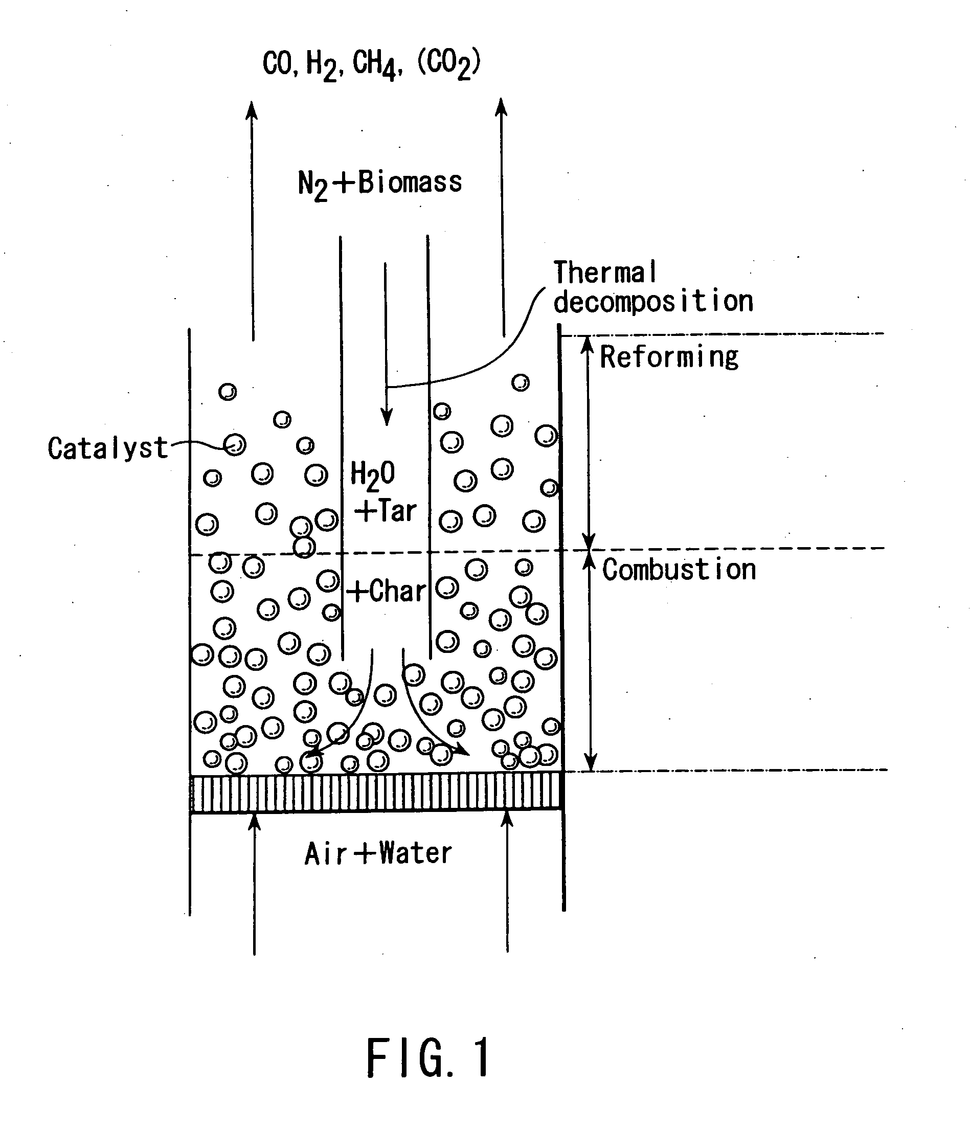
[0041] Specifically, cellulose particles manufactured by Merck Inc. and having a particle diameter of 100 to 160 μm were gasified by using the apparatus schematically shown in FIG. 1.

[0042] A container made of glass was used as a feeder, and a glass cock for controlling the supply was formed in a bottom portion of the feeder. Cellulose particles were supplied into a catalyst bed by using an N2 gas stream passing through an inner tube having inner diameters of 5 mm and 8 mm. The gasification reactor was formed of a quartz tube having a height of 66 cm and an inner diameter of 1.8 cm and included a fluidized bed portion. Air and water were introduced into the gasification reactor from the bottom portion so as to reach the catalyst bed through a quartz dispersion plate. Steam was supplied by using a micro feeder. Water that was evaporated during its upward movement through a capillar...


PUM

PropertyMeasurementUnit
temperaturesaaaaaaaaaa
specific surface areaaaaaaaaaaa
particle diameteraaaaaaaaaa

Abstract

Disclosed is a method of gasifying a biomass, comprising heating a fluidized bed reactor loaded with a catalyst represented by Rh / CeO2 / M, where M represents SiO2, Al2O3 or ZrO2, to temperatures lower than 800° C. introducing biomass particles into the fluidized bed reactor from an upper portion thereof, introducing air and steam into the fluidized bed reactor from a lower portion thereof, and allowing the biomass particles to react at the surface of the Rh / CeO2 / M catalyst so as to manufacture hydrogen and a syngas.

Description

CROSS-REFERENCE TO RELATED APPLICATIONS [0001] This application is based upon and claims the benefit of priority from the prior Japanese Patent Application No. 2001-384857, filed Dec. 18, 2001, the entire contents of which are incorporated herein by reference. BACKGROUND OF THE INVENTION [0002] 1. Field of the Invention [0003] The present invention relates to a method of gasifying a biomass and a catalyst used for the gasifying method. [0004] 2. Description of the Related Art [0005] In general, the manufacture of a syngas by Utilizing gasification of a biomass such as cellulose is carried at a high temperature of at least 800° C. If the syngas is manufactured at temperatures lower than 800° C., the biomass is partly converted into tar or char, resulting in failure to carry out a stable operation. The formation of tar or char tends to increase with decrease in the reaction temperature, with the result that it is considered difficult to gasify the biomass under low temperatures. [0006...

Claims


Application Information

Patent Timeline
Patent Type & Authority Applications(United States)
IPC IPC(8): C01B3/32B01J23/63B01J35/00B01J37/02C10J3/46
CPCB01J23/63B01J35/023B01J35/10B01J35/1014B01J35/1019B01J37/0205C10K3/006C10J2300/0916C10J2300/092C10J2300/0956C10J2300/0973C10J2300/0983C10J2300/0986C10J3/482Y02P20/145Y02P20/52B01J35/40B01J35/60B01J35/613B01J35/615
Inventor YAMADA, MUNEYOSHITOMISHIGE, KEIICHIASADULLAH, MOHAMMADKUNIMORI, KIMIO
Owner TOHOKU UNIV
Learn More