
Azimuth processing device, azimuth processing method, azimuth processing program, direction finding device, tilt offset correcting method, azimuth measuring method, compass sensor unit, and portable electronic device

a technology of azimuth processing and compass sensor, which is applied in the direction of surveying and navigation, navigation instruments, instruments, etc., can solve the problems of user dropping equipment, calibration procedure is difficult to perform correctly, and accuracy of offset cannot be calculated from measurement data, so as to reduce the work of sensitivity correction

Inactive Publication Date: 2006-02-09
YAMAHA CORP
View PDF35 Cites 52 Cited by
  • Summary
  • Abstract
  • Description
  • Claims
  • Application Information

AI Technical Summary

Benefits of technology

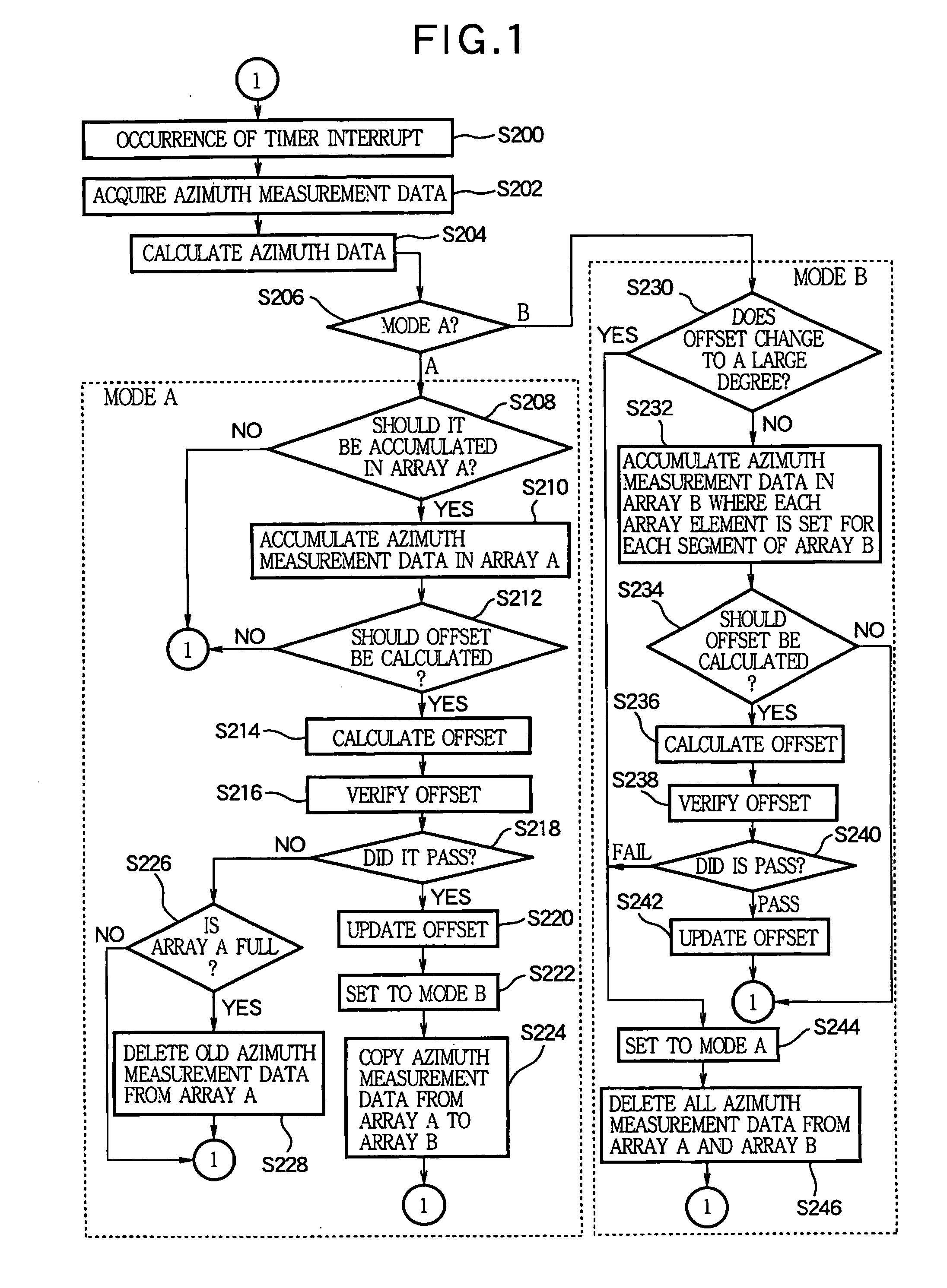
[0012] Since the measurement data are selectively accumulated, the accuracy of offset data updated based on the accumulated measurement data is improved. The offset data is data representing the above-mentioned offset, that is, indicating a deviation of the measurement data of the compass sensor. The azimuth processing device outputs azimuth data according to a difference between the measurement data and the offset data. Specifically, for example, in the case of a three-axis compass sensor for detecting the strength and direction of a magnetic field resolved along three axes orthogonal to one another, the relationship among the measurement data (x, y, z), the offset data (x0, y0, z0), and the azimuth data (X, Y, Z) is as follows: (X, Y, Z)=(x−x0, y−y0, z−z0)
[0096] Work for sensitivity correction can be reduced by measuring the azimuth while compensating the sensitivity of the tilt sensor as well as calibration of the geomagnetic sensor and the tilt sensor.

Problems solved by technology

However, the user might drop the equipment during the calibration.
Further, even when the user completed calibration, accurate offset might not be able to be calculated from measurement data from the compass sensor accumulated during the calibration.
Furthermore, the calibration procedure is hard to perform correctly without reading the manual or the like.
Since the procedure is necessary only to update the offset of the compass sensor, it is burdensome for the user to follow.
Therefore, it requires much effort to check and correct sensitivity in a product line.

Method used


Image

  • Azimuth processing device, azimuth processing method, azimuth processing program, direction finding device, tilt offset correcting method, azimuth measuring method, compass sensor unit, and portable electronic device
  • Azimuth processing device, azimuth processing method, azimuth processing program, direction finding device, tilt offset correcting method, azimuth measuring method, compass sensor unit, and portable electronic device
  • Azimuth processing device, azimuth processing method, azimuth processing program, direction finding device, tilt offset correcting method, azimuth measuring method, compass sensor unit, and portable electronic device

Examples


first embodiment

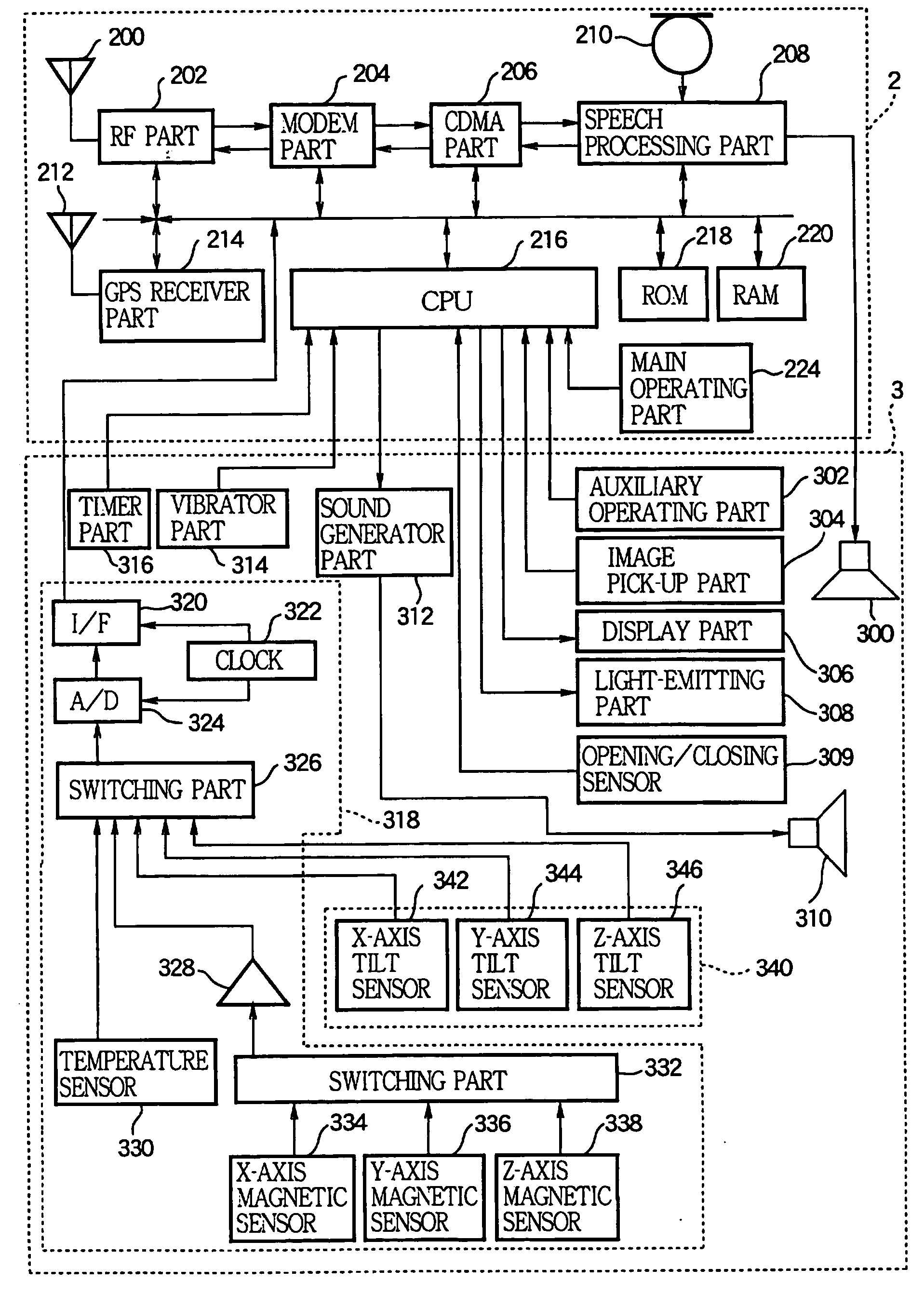
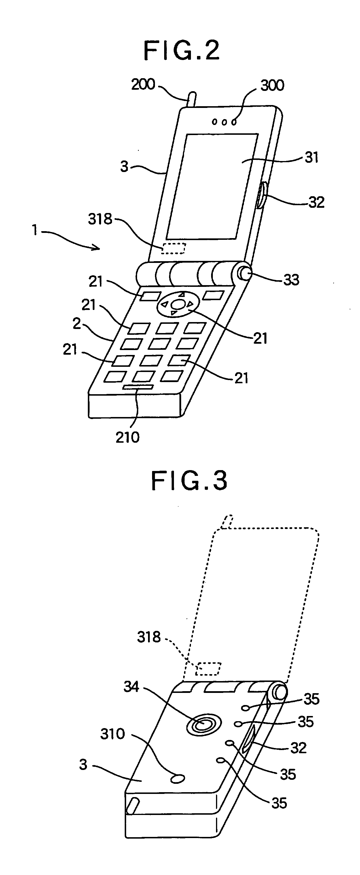
[0144]FIGS. 2 and 3 are external views showing a telephone 1 as a portable electronic device according to a first embodiment of the present invention. The telephone 1 is a portable, compact telephone having a wireless phone-call function and a function for displaying a map around its current position. The telephone 1 consists predominantly of an operation unit 2 with multiple keys 21, and a display unit 3 with a screen 31. The display unit 3 is coupled swingablly to the operation unit 2. FIG. 3 shows such a state that the display unit 3 is folded over the operation unit 2. In this state, the keys 21 on the operation unit 2 are covered by the display unit 3, while the screen 31 on the display unit 3 is covered by the operation unit 2. When a button 33 is pressed in such a state that the display unit 3 is folded over the operation unit 2, the elastic force of a spring, not shown, causes the display unit 3 to swing up from the operation unit 2.

[0145]FIG. 4 is a block diagram showing t...

second embodiment

[0235] The following describes a second embodiment. In the second embodiment, the controller 40 starts accumulation of azimuth measurement data necessary to calculate azimuth data in synchronization with the user's action to swing up the display unit 3 from the operation unit 2, that is, to open the display unit 3. In the first embodiment, the controller 40 starts accumulation of azimuth measurement data upon starting of the geographic information display program to update azimuth offset data and azimuth data in parallel. On the other hand, in the second embodiment, it starts accumulation of azimuth measurement data when the opening / closing sensor 309 detects the start of opening of the display unit 3.

[0236]FIGS. 17 and 18 are flowcharts showing an azimuth processing method according to the second embodiment of the present invention. Substantially the same processing steps as those in the first embodiment are given the same numerals, and the description thereof is omitted.

[0237] W...

third embodiment

[0244] After closing the display unit 3, the user is likely to put the telephone 1 in a pocket, on a desk, or in a bag. In such an action, the telephone 1 changes its attitude or position in a complicated manner. Further, since the compass sensor module 318 incorporated in the display unit 3 changes its attitude or position with closing of the display unit 3, the change in its attitude becomes more complicated.

[0245] Therefore, the controller 40 may start accumulation of azimuth measurement data necessary to calculate azimuth data in conjunction with the movement of the display unit 3 closer to the operation unit 2, that is, closing of the display unit 3. In other words, it may perform processing for detecting the start of closing of the display unit 3 instead of the processing step S400 in the second embodiment.


PUM


Abstract

An azimuth processing device is designed for outputting azimuth data based on measurement data sequentially output from a compass sensor. In the device, an accumulation section selectively accumulates substantially new pieces of the measurement data. An offset data updating section updates offset data of the compass sensor based on plural pieces of the measurement data accumulated by said accumulation section. An azimuth data output section outputs the azimuth data based on substantially newest measurement data and the offset data.

Description

BACKGROUND OF THE INVENTION [0001] 1. Technical Field [0002] The present invention relates to an azimuth processing device, an azimuth processing method, an azimuth processing program, a direction finding device, a tilt offset correcting method, azimuth measuring method, a compass sensor unit, and a portable electronic device. In particular, the present invention relates to estimating and updating of an offset of the compass sensor. [0003] 2. Background Art [0004] Some recent portable information terminals, such as cellular phones and PDAs, have a function for displaying geographic information using GPS and a compass sensor. For example, a portable information terminal is known, which determines its current position using GPS, downloads map information around the current position from a server via a communication line, determines azimuth heading with a built-in compass sensor, and displays the map information on a screen in such a manner to orient the map heading to the actual azimu...

Claims


Application Information

Patent Timeline
Patent Type & Authority Applications(United States)
IPC IPC(8): G01C21/28
CPCG01C17/38
Inventor SATO, HIDEKIYAMAKI, KIYOSHIOMURA, MASAYOSHIOSUGA, CHIHIRONIHASHI, SATOSHIMABUCHI, TETSUYA
Owner YAMAHA CORP
Learn More