
Method of calculating the amount of work done by an internal combustion engine

Inactive Publication Date: 2006-02-09
HONDA MOTOR CO LTD
View PDF3 Cites 4 Cited by
  • Summary
  • Abstract
  • Description
  • Claims
  • Application Information

AI Technical Summary

Benefits of technology

[0013] With the configuration of the method according to the first aspect of present invention, pressure in the combustion chamber is detected to obtain in-cylinder-pressure data indicative of the obtained pressure, and volume data indicative of a state of change in the volume of the combustion chamber is subjected to a first predetermined filtering process. Then, a work amount parameter is calculated based on the volume data subjected to the first filtering process and the in-cylinder pressure data. Therefore, when a phase delay of the in-cylinder pressure data is generated e.g. due to a filtering process for eliminating noises from the in-cylinder pressure data or the response delay of a sensor that detects the in-cylinder pressure, the relative phase deviation between the in-cylinder pressure data and the volume data can be eliminated e.g. by imparting the same phase delay as the phase delay of the in-cylinder pressure data to the volume data through the first filtering process. This makes it possible to calculate the work amount parameter with accuracy while properly compensating for the phase delay of the in-cylinder pressure data.
[0018] With the configuration of the method according to the second aspect of the present invention, in-cylinder pressure is-detected to obtain in-cylinder pressure data indicative of the detected pressure, and a predetermined reference signal is subjected to a first predetermined filtering process. Then, a work amount parameter is calculated based on the reference signal subjected to the first filtering process and the in-cylinder pressure data. Therefore, when a phase delay of the in-cylinder pressure data is generated e.g. by a filtering process performed thereon, the relative phase deviation between the in-cylinder pressure data and the reference signal can be eliminated e.g. by imparting the same phase delay as the phase delay of the in-cylinder pressure data to the reference signal through the first filtering process. This makes it possible to calculate the work amount parameter with accuracy while properly compensating for the phase delay of the in-cylinder pressure data.
[0020] With the configuration of the preferred embodiment, a correlation coefficient between the in-cylinder pressure data and the reference signal is calculated based on the in-cylinder pressure data and the reference signal subjected to the first filtering process, and the work amount parameter is calculated based on the calculated correlation coefficient. As a result, when a phase delay of the in-cylinder pressure data is generated, the relative phase deviation between the-in-cylinder pressure data and the reference signal can be eliminated e.g. by imparting the same phase delay as the phase delay of the in-cylinder pressure data to the reference signal through the first filtering process. This makes it possible to properly calculate the correlation coefficient while properly compensating for the phase delay of the in-cylinder pressure data, and hence the work amount parameter can be calculated with accuracy.
[0024] In contrast, according to the present invention, the in-cylinder pressure data is subjected to the second filtering process before it is sampled at the second repetition period. In this case, for example, the second filtering process is performed to eliminate components of the in-cylinder pressure data in a frequency range (hereinafter referred to as “the predetermined frequency range”) not lower than the half of a frequency corresponding to the second repetition period, whereby the components in the predetermined frequency range are eliminated in advance before sampling of the in-cylinder pressure data. As a result, even if the in-cylinder pressure data is sampled at the second repetition period longer than the first repetition period, which can cause aliasing, it is possible to prevent aliasing from being caused by the sampling, thereby making it possible to prevent distortion of the in-cylinder pressure caused by the aliasing.
[0025] Further, the phase delay of the in-cylinder pressure data caused by the second filtering process can be properly compensated for e.g. by performing the first filtering process using a filter having the same characteristic as that of a filter used in the second filtering process to thereby impart the same phase delay as the phase delay of the in-cylinder pressure data to the volume data or the reference signal to thereby eliminate the relative phase deviation between the in-cylinder pressure data and the volume data or the reference signal. This makes it possible to calculate the work amount parameter with accuracy while preventing aliasing and properly compensating for the phase delay of the in-cylinder pressure data. It should be noted that although in the second filtering process, the components of the in-cylinder pressure data in the frequency range not lower than the half of the frequency corresponding to the second repetition period are eliminated, as described above, components of the in-cylinder pressure data in a frequency range not lower than a predetermined frequency higher than the half of the frequency corresponding to the second repetition period may be eliminated so long as the result of calculation of the work amount parameter is not affected by aliasing. Furthermore, the in-cylinder pressure data sampled at the second repetition period longer than the first repetition period is used for calculation of the work amount parameter, which makes it possible to reduce the number of data items necessary for the calculation, which contributes to thinning of the data. Therefore, it is possible to decrease computation load of the work amount parameter.

Problems solved by technology

In the above conventional method, however, there can occur a large error in the calculated indicated mean effective pressure.
More specifically, an in-cylinder pressure signal indicative of the detected pressure in the combustion chamber delivered from the in-cylinder pressure sensor, as described above, usually contains noises, and hence if in-cylinder pressure determined based on the in-cylinder pressure signal is used as it is for calculation of the indicated mean effective pressure, there is a fear that the calculated indicated mean effective pressure contains a large error due to influence of the noises.
In this case, however, the low-pass filter generally has a characteristic that it delays the signal as it filters the same, and the delay is increased as the cutoff frequency of the low-pass filter is lower.
This causes a relatively large phase delay of the filtered in-cylinder pressure with respect to the actual in-cylinder pressure.
Therefore, due to the large phase delay which the in-cylinder pressure experiences as described above, the calculated indicated mean effective pressure comes to suffer from a significant error or difference from the proper value.

Method used


Image

  • Method of calculating the amount of work done by an internal combustion engine
  • Method of calculating the amount of work done by an internal combustion engine
  • Method of calculating the amount of work done by an internal combustion engine

Examples


first embodiment

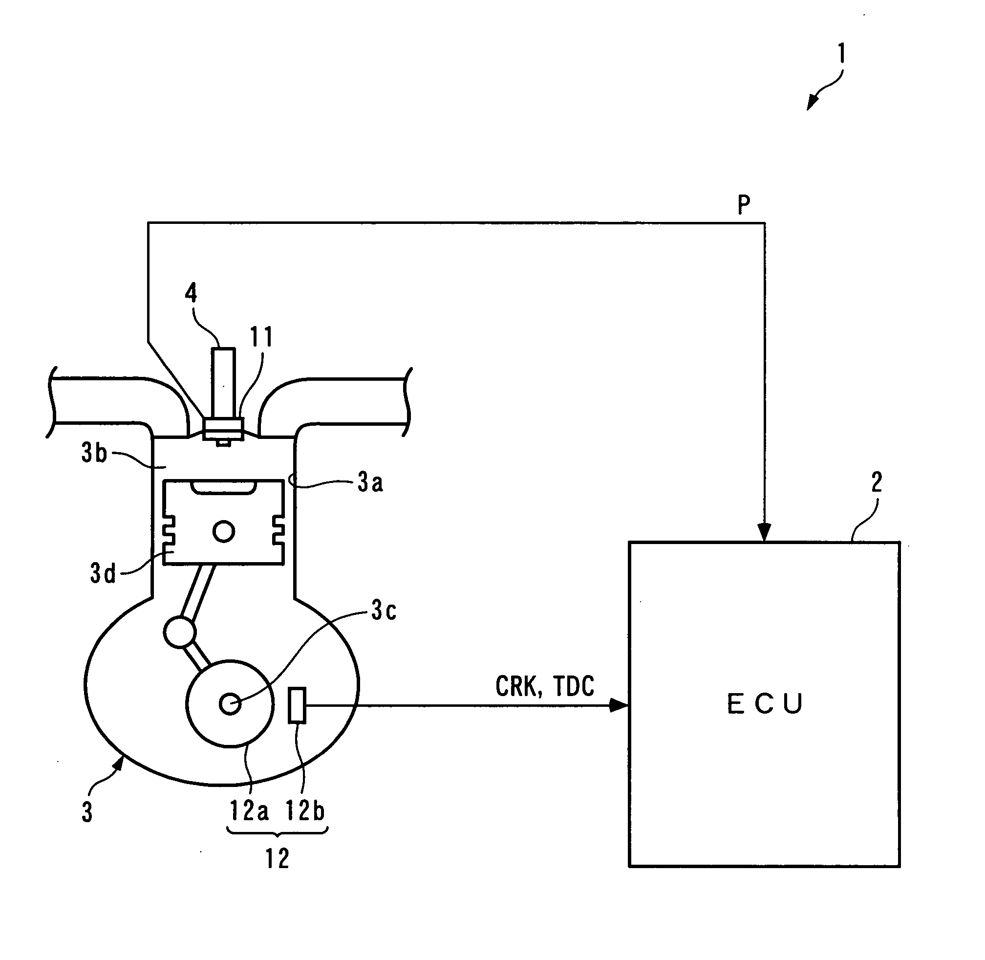
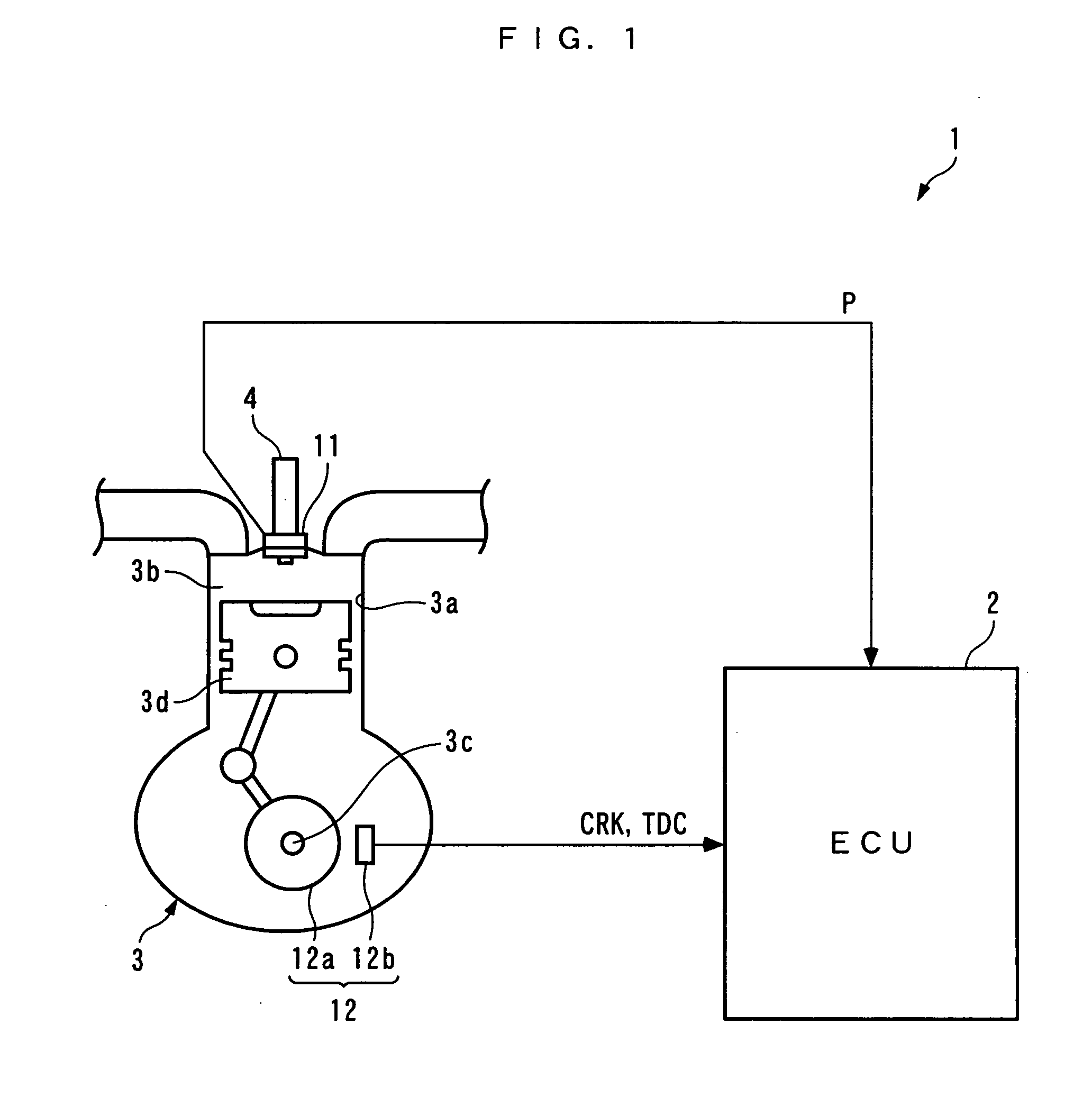
[0041] The invention will now be described in detail with reference to the drawings showing a method of calculating an indicated mean effective pressure Pmi (work amount parameter) in an internal combustion engine, according to the present invention. FIG. 1 is a schematic diagram of a calculation device 1 for calculating the indicated mean effective pressure Pmi by the method according to the present invention, and an internal combustion engine (hereinafter referred to as “the engine”) 3 to which the calculation device 1 is applied. The calculation device 1 includes an ECU 2, referred to hereinafter. The engine 3 is e.g. a four-stroke cycle gasoline engine, installed on a vehicle, not shown.

[0042] Spark plugs 4 are mounted through respective cylinder heads of cylinders 3a of the engine 3 in a manner facing a combustion chamber 3b. Each spark plug 4 has an in-cylinder pressure sensor 11 integrally mounted thereon. The in-cylinder pressure sensor 11 is e.g. of a piezoelectric element ...

second embodiment

[0091] Further, similarly to the second embodiment, the volume data V is filtered by the volume data filter 31c having the same characteristic as that of the in-cylinder pressure filter 31a, and hence it is possible to eliminate the relative phase deviation between the in-cylinder pressure filtered value PF and the volume data filtered value VF, thereby making it possible to properly compensating for the phase delay of the in-cylinder pressure filtered value PF. Therefore, it is possible to calculate the indicated mean effective pressure Pmi with accuracy while preventing aliasing and properly compensating for the phase delay of the in-cylinder pressure filtered value PF. Furthermore, since the in-cylinder pressure filtered value PF(n) down-sampled whenever the first CRK signal is inputted is used for calculation of the indicated mean effective pressure Pmi, the number of data items necessary for the calculation can be reduced to thin the data, thereby making it possible to decrease...


PUM


Abstract

A method of calculating the amount of work done by an internal combustion engine, which is capable of calculating a work amount parameter indicative of the amount of work done with accuracy while compensating for a phase delay in in-cylinder pressure data caused e.g. by a filtering process performed thereon. The method calculates the work amount parameter Pmi indicative of the amount of work done by the engine 3 including a combustion chamber 3b, as follows: Pressure in the combustion chamber 3b is detected to obtain in-cylinder pressure data P indicative of the detected pressure. Volume data V indicative of a state of change in volume of the combustion chamber 3b is obtained. The obtained volume data V is subjected to a first predetermined filtering process. The work amount parameter Pmi is calculated based on the detected in-cylinder pressure data P, and the volume data filtered value VF obtained by subjecting the volume data V to the first filtering process.

Description

BACKGROUND OF THE INVENTION [0001] 1. Field of the Invention [0002] This invention relates to a method of calculating a work amount parameter, such as indicated mean effective pressure, which is indicative of the amount of work done by an internal combustion engine. [0003] 2. Description of the Related Art [0004] Conventionally, a method of calculating indicated mean effective pressure has been disclosed e.g. in Japanese Laid-Open Patent Publication (Kokai) No. H11-182319. In this method, the indicated mean effective pressure is calculated as follows: In-cylinder pressure, i.e. pressure in a combustion chamber of an internal combustion engine, is detected by an in-cylinder pressure sensor of a piezoelectric element type which is mounted to a spark plug of the engine. Then, the indicated mean effective pressure is calculated by subtracting a value obtained by integrating the product of the detected in-cylinder pressure and the rate of change in volume of the combustion chamber (herei...

Claims


Application Information

Patent Timeline
IPC IPC(8): G06F19/00F02D45/00
CPCG01L3/245G01M15/08G01M15/044
Inventor SHINOZAKI, KOICHIROOKUBO, KATSURAYASUI, YUJISATO, MASAHIRO
Owner HONDA MOTOR CO LTD
Learn More