
Tire information detecting apparatus without distortion

Inactive Publication Date: 2006-03-09
ALPS ALPINE CO LTD
View PDF5 Cites 0 Cited by
  • Summary
  • Abstract
  • Description
  • Claims
  • Application Information

AI Technical Summary

Benefits of technology

[0009] An advantage of the invention is that it prevents the distortion due to the modulation, by causing a sensor of a responder to excite by using an interrogation signal to be output from the controller (interrogator) as a non-modulation signal
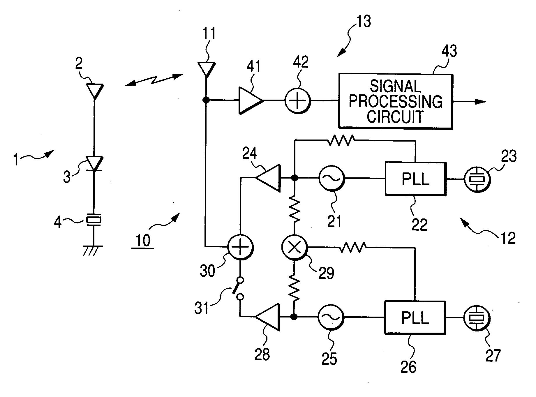
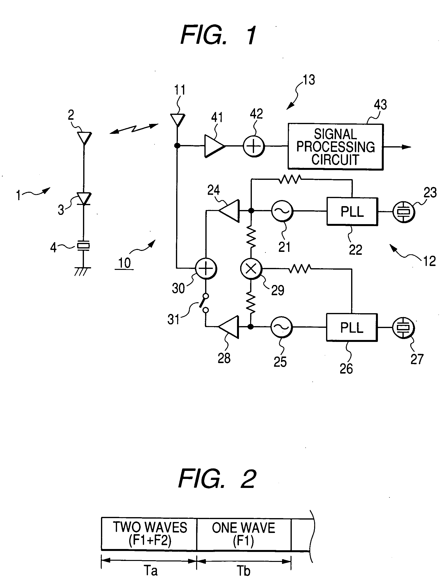
[0010] In order to solve the problems, a tire information detecting apparatus includes an interrogator which transmits an interrogation signal toward a tire in a vehicle at a transmitting timing, and receives a reply signal including tire information such as a tire pneumatic pressure at a receiving timing so as to process the signals, a responder which has a sensor being excited by a predetermined frequency signal to detect the tire information and is disposed in the tire to return the reply signal to the interrogator at the receiving timing in responding to the interrogation signal, and a mixer unit which receives the interrogation signal having a first signal and a second signal which is spaced the predetermined frequency away from the first signal, from the interrogator, and outputs a signal of the frequency difference between the two signals to the responder by mixing the first and second signals.
[0011] In addition, only the first signal is transmitted at the receiving timing.
[0012] The interrogator includes a first voltage-controlled oscillator for outputting the first signal, a first PLL circuit to which a first reference signal is input and which controls the first voltage-controlled oscillator, a second voltage-controlled oscillator for outputting the second signal, a second PLL circuit to which a second reference signal is input and which controls the second voltage-controlled oscillator. The first signal is input to the first PLL circuit, and the signal of the frequency difference between the first and second signals is input to the second PLL circuit.
[0013] The level of the first signal is set to be equal to the level of the second signal.
[0014] According to a first aspect of the invention, a tire information detecting apparatus includes an interrogator which transmits an interrogation signal toward a tire in a vehicle at a transmitting timing, and receives a reply signal including tire information such as a tire pneumatic pressure at a receiving timing so as to process the signals, a responder which has a sensor being excited by a predetermined frequency signal to detect the tire information and is disposed in the tire to return the reply signal to the interrogator at the receiving timing in responding to the interrogation signal, and a mixer unit which receives the interrogation signal having a first signal and a second signal which is spaced the predetermined frequency away from the first signal, from the interrogator, and outputs a signal of the frequency difference between the two signals to the responder by mixing the first and second signals. Therefore, only transmitting a signal of two waves instead of transmitting an amplitude modulation wave from the interrogator can cause the sensor to excite. Accordingly, the spurious problem due to the distorted amplitude-modulation wave can be prevented. Further, although the modulation level is lowered, it is impossible to cause the sensor to sufficiently excite.

Problems solved by technology

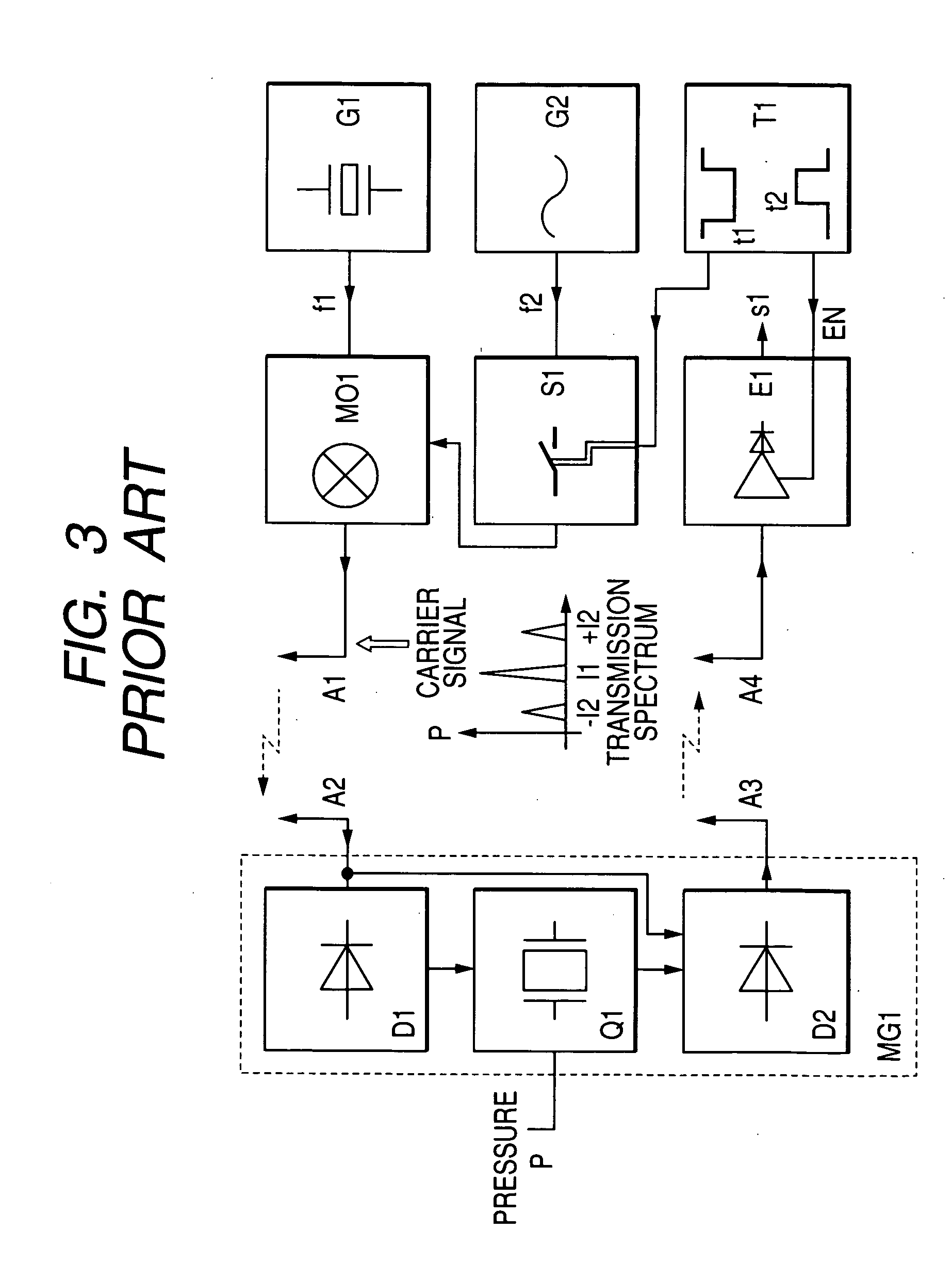
On the other hand, when the modulation degree increases to cause the crystal resonator to easily excite, the modulation wave is greatly distorted, thereby causing a spurious problem.
Further, if the modulation degree decreases in order to escape the problem, the modulation level is lowered, whereby it is impossible to cause the crystal resonator to sufficiently excite.

Method used


Image

  • Tire information detecting apparatus without distortion
  • Tire information detecting apparatus without distortion
  • Tire information detecting apparatus without distortion

Examples


Embodiment Construction

[0021] Hereinafter, a tire information detecting apparatus of the invention will now be described with reference to the accompanying drawings. In FIG. 1, a responder 1 is mounted in a tire (not shown) in a vehicle. An interrogator 10 is disposed in a vehicle main body (not shown).

[0022] The responder 1 includes an antenna 2, a mixer unit 3 which is coupled to the antenna 2, and a sensor 4 which is coupled to the mixer unit 3. The mixer unit 3 is composed of non-linear elements such as a diode and functions as a frequency converting unit and a modulating unit. In addition, the sensor 4 is composed of a crystal resonator that is self-resonated when being excided by a self-resonant frequency or a frequency (for example, about 10 MHz) close to the self-resonant frequency. The resonant frequency varies on the basis of the tire pneumatic pressure or the temperature of the tire. Sensors 4 are plurally provided corresponding to tire information to be detected.

[0023] The interrogator 10 ha...


PUM


Abstract

A tire information detecting apparatus includes an interrogator which transmits an interrogation signal toward a tire in a vehicle at a transmitting timing, and receives a reply signal including tire information at a receiving timing so as to process the signals. A responder is disposed in the tire and has a sensor excited by a predetermined frequency signal for detecting tire information so as to return the reply signal to the interrogator at the receiving timing in responding to the interrogation signal. A mixer unit which receives the interrogation signal having a first signal and a second signal which is spaced the predetermined frequency away from the first signal, from the interrogator, and outputs a signal of the frequency difference between the two signals to the responder by mixing the first and second signals.

Description

BACKGROUND OF THE INVENTION [0001] 1. Field of the Invention [0002] The present invention relates to a tire information detecting apparatus for monitoring the pneumatic pressure of tires [0003] 2. Description of the Related Art [0004] A tire information detecting apparatus according to the related art will be described with reference to FIG. 3. A controller includes at least one generator G1 for generating radio frequency with respect to a carrier signal f1 at a microwave frequency band of about 2.4 GHz. The carrier signal f1 is modulated by at least one low frequency signal f2 which is generated by a generator G2 and preferably at a frequency band in the range of 1 to 30 MHz. As a result of the modulation, a desired supply frequency is generated. A signal of the generated frequency is amplified and transmitted via an antenna A1 disposed around a tire. [0005] Preferably, the modulation means an amplitude modulation. According to the above-mentioned modulation method, a sideband is g...

Claims


Application Information

Patent Timeline
IPC IPC(8): B60R25/10B60C23/04G08C17/00G08C17/02G08C19/00G08C19/12
CPCB60C23/0433B60C23/0408
Inventor IIJIMA, KOUTA
Owner ALPS ALPINE CO LTD
Learn More