
Intraluminal stent assembly and method of deploying the same

a technology of stent and assembly, which is applied in the field of intraluminal stent assembly and the same, can solve the problems of stent to “jump” or slip, death, disability, healthcare expense,

Inactive Publication Date: 2006-02-09
MEDTRONIC VASCULAR INC
View PDF17 Cites 43 Cited by
  • Summary
  • Abstract
  • Description
  • Claims
  • Application Information

AI Technical Summary

Problems solved by technology

Heart disease, specifically coronary artery disease, is a major cause of death, disability, and healthcare expense.
While vessel restenosis may not occur in the majority of cases, it occurs frequently enough that such complications comprise a significant percentage of the overall failures of the PTCA procedure, for example, twenty-five to thirty-five percent of such failures.
Some difficulties have been encountered with the deployment of certain self-expanding stents, including difficulties related to placement accuracy.
As the stent expands beyond the end of the sheath, the stored energy may be immediately released, causing the stent to “jump” or slip.
This may result in an inaccurate placement of the stent within the body vessel.

Method used


Image

  • Intraluminal stent assembly and method of deploying the same
  • Intraluminal stent assembly and method of deploying the same
  • Intraluminal stent assembly and method of deploying the same

Examples


Embodiment Construction

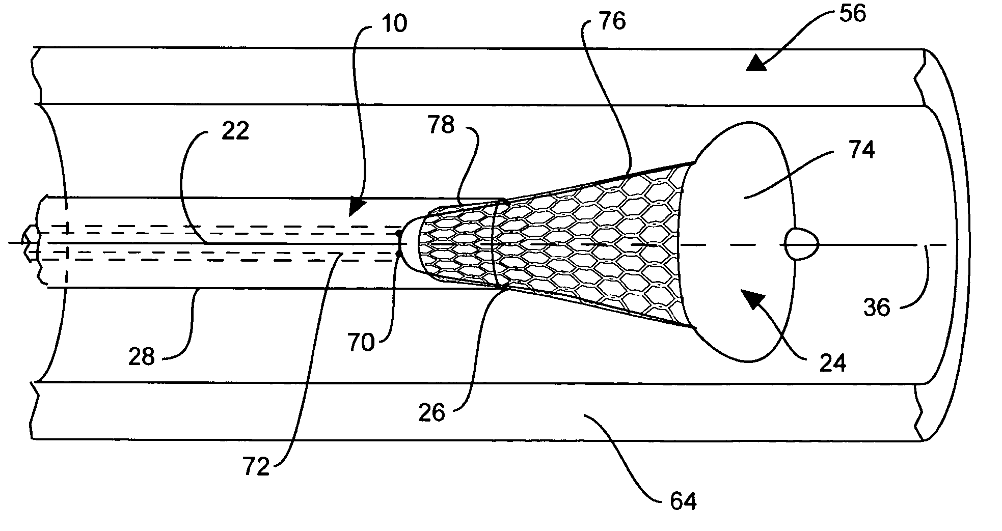
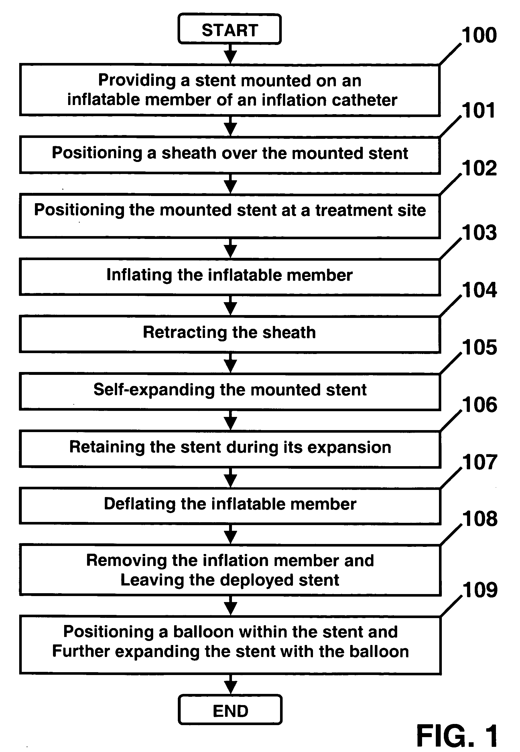
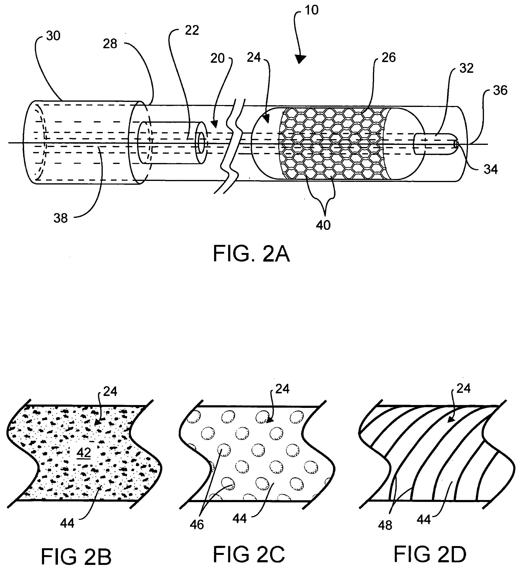
[0024] Referring to the drawings, wherein like reference numerals refer to like elements, FIG. 1 is a flow chart of one embodiment of a method of deploying an intraluminal stent in a patient, in accordance with the present invention. The following description relates primarily to the deployment of an intravascular, self-expanding stent following a balloon angioplasty procedure. Those skilled in the art will recognize that although the present invention is described primarily in the context of deploying a stent in a coronary artery with a specific intraluminal stent assembly, the inventor contemplates numerous other applications and variations to the stent assembly. For example, an intraluminal device according to the invention may be deployed within another blood vessel, arteriole or venous valve, intestine, air duct, esophagus, bile duct, and the like. Any number of devices capable of performing the prescribed function(s) may be adapted for use with the present invention. Furthermo...


PUM


Abstract

Intraluminal stent assemblies and methods of deploying the same. The assemblies include a catheter including at least one lumen formed therein. At least one inflatable member is disposed on the catheter and in communication with the lumen. The inflatable member includes at least one distal projection and / or at least one retention material. A stent is expandable from a compressed configuration to an expanded configuration. The stent is disposed on the inflatable member in the compressed configuration. A sheath is slidably positioned over the stent wherein the stent expands to the expanded configuration upon retraction of the sheath. The inflatable member is inflated with a fluid flowing through the lumen. The at least one distal projection and / or at least one retention material retain the stent in position on the inflatable member while the stent is being deployed.

Description

TECHNICAL FIELD OF THE INVENTION [0001] The present invention relates generally to medical catheters. More particularly, the invention relates to an intraluminal stent assembly and method of deploying the same. BACKGROUND OF THE INVENTION [0002] Heart disease, specifically coronary artery disease, is a major cause of death, disability, and healthcare expense. A number of strategies have been developed for treating coronary heart disease, some of which are specifically designed to treat the complications resulting from atherosclerosis and other forms of coronary arterial narrowing. [0003] An important development for treating atherosclerosis and other forms of coronary narrowing is percutaneous transluminal coronary angioplasty, hereinafter referred to as “angioplasty” or “PTCA”. One objective in angioplasty is to enlarge the lumen of the affected coronary artery by radial hydraulic expansion. The procedure may be accomplished by inflating a balloon within the narrowed lumen of the c...

Claims


Application Information

Patent Timeline
Patent Type & Authority Applications(United States)
IPC IPC(8): A61F2/06
CPCA61F2/958
Inventor DOLAN, MARK J.
Owner MEDTRONIC VASCULAR INC
Learn More