
Windowed optical system having a tilted optical element to correct aberrations

Active Publication Date: 2006-02-09
RAYTHEON CO
View PDF17 Cites 13 Cited by
  • Summary
  • Abstract
  • Description
  • Claims
  • Application Information

AI Technical Summary

Benefits of technology

[0012] The present approach avoids the use of an asymmetric decentered optical corrector in relation to an off-boresight optical system with an optical path that passes through a dome window. Such decentered optical correctors may be difficult to fabricate, test, mount, and align, and increase the piece count of the system. They also add to the weight of the system.
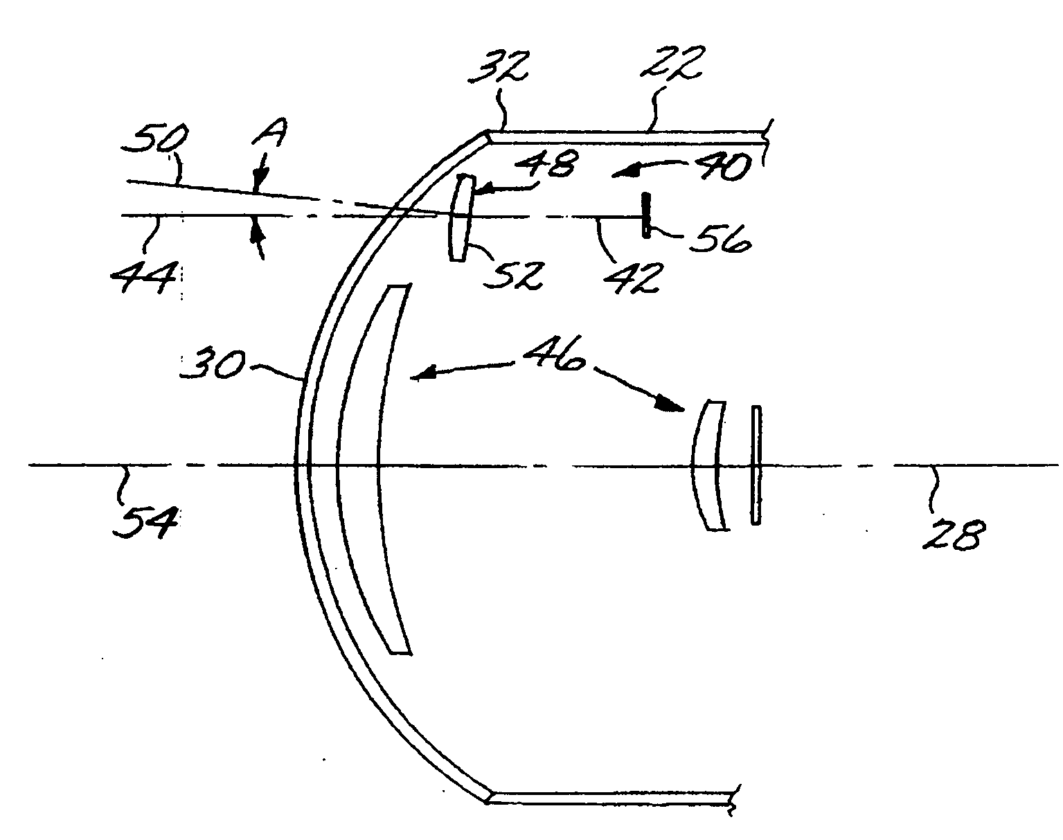
[0013] Instead, an existing optical element used in the imaging system is tilted slightly in the optical path to compensate for the aberrations introduced when the optical path passes through the dome window. The optical compensation achieved with the present approach is comparable to, but not quite as good as, that achieved with the use of an asymmetric decentered optical corrector. However, for many applications the present approach produces satisfactory optical results, and has the important advantage of avoiding the use of the asymmetric decentered optical corrector and the associated problems and limitations.

Problems solved by technology

This approach, while operable, has drawbacks.
Specifically, the fabrication, testing, mounting, and alignment of the decentered optical corrector segment are difficult, and the piece count of the system is high.

Method used


Image

  • Windowed optical system having a tilted optical element to correct aberrations
  • Windowed optical system having a tilted optical element to correct aberrations
  • Windowed optical system having a tilted optical element to correct aberrations

Examples


Embodiment Construction

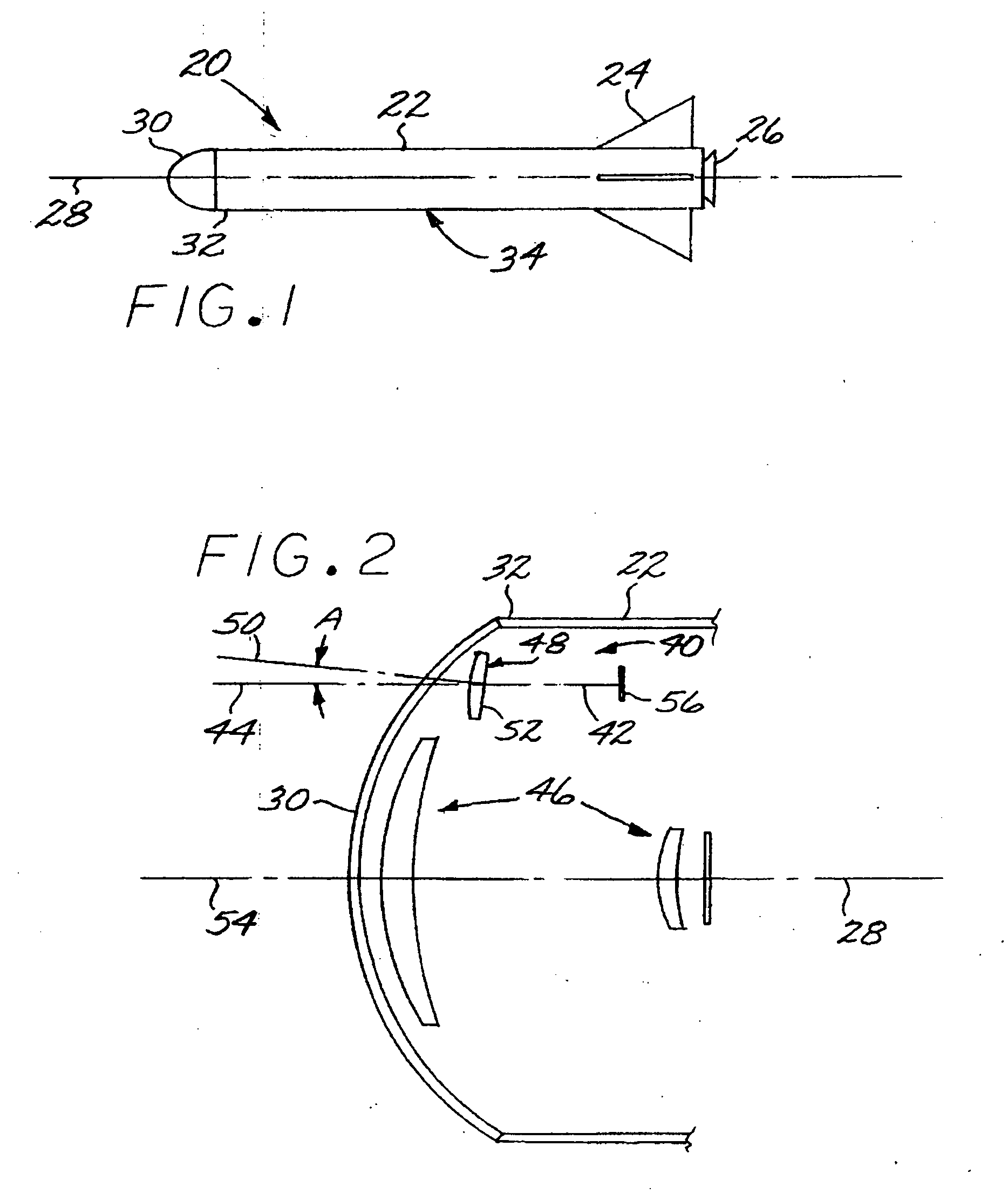
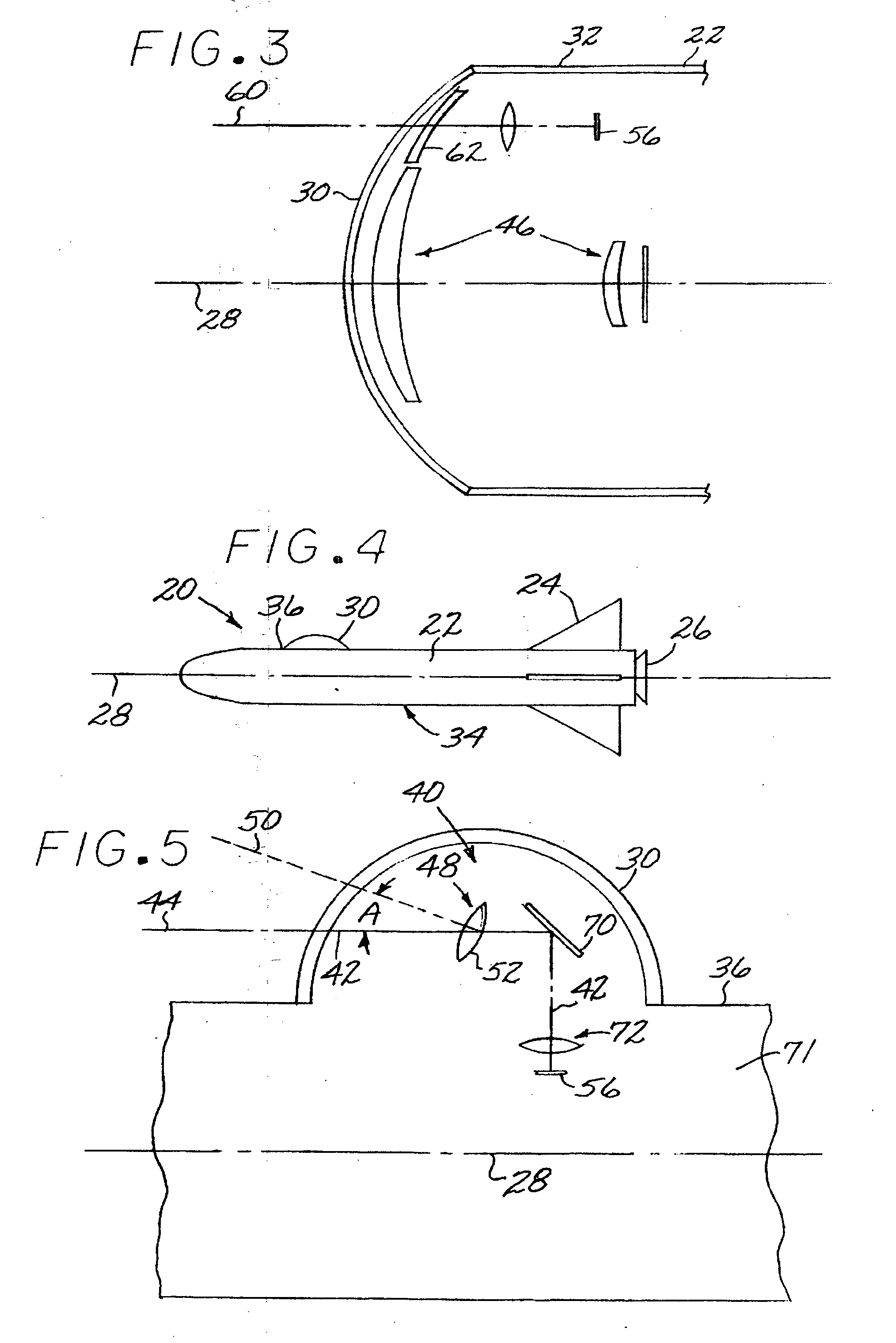
[0022]FIG. 1 depicts an aircraft 20, in this case an unmanned missile. The aircraft 20 includes a fuselage 22, control surfaces 24 affixed to the fuselage 22, and optionally a propulsion motor 26 such as a rocket engine within the fuselage 22. The fuselage 22 has a longitudinal axis of symmetry, termed a boresight axis 28. There is a dome window 30 affixed to a forward end (i.e., nose) 32 of the fuselage 22. The dome window 30 may be spherical or non-spherical in shape. The fuselage 22 serves as a housing 34 for at least a portion of an optical system to be discussed subsequently. While the fuselage 22 of the unmanned missile aircraft 20 is the currently preferred housing 34, other types of housings such as manned aircraft or other structures may be used as well.

[0023]FIG. 2 depicts an optical system 40 having a central optical path 42 that passes through the dome window 30 mounted to the forward end 32 of the fuselage 22. The illustrated central optical path 42 of the optical syst...


PUM


Abstract

A system comprises a dome window and an optical system having a central optical path that passes through the dome window. The optical system includes a refractive optical element having an axis of symmetry which passes through the optical element and which is tilted relative to the central optical path at a location where the central optical path and the axis of symmetry intersect within the optical element.

Description

[0001] This invention relates to optical systems and, more particularly, to the correction of aberrations produced when the central optical path of the optical system passes through a concentric dome window. BACKGROUND OF THE INVENTION [0002] Many advanced missiles utilize a generally forward-facing optical sensor to guide the missile to its target. The sensor (or, equivalently for the present purposes, a portion of the optical train that directs the incoming optical rays along an optical path from the scene to the sensor) is usually pivotably mounted so that the sensor may be directed to point in directions other than along the boresight axis (i.e., the axis of symmetry of the fuselage) of the missile. The sensor views the scene in front of the missile through a forward-facing dome window. The dome window protects the sensor from the high-velocity air stream and from impacts by water droplets, ice, dust, and other particles that are present in the air. [0003] In some designs, the o...

Claims


Application Information

Patent Timeline
IPC IPC(8): G02B9/00
CPCG02B27/0025
Inventor SPARROLD, SCOTT
Owner RAYTHEON CO
Learn More