
Zoom lens, video enlarging/projecting system, video projector, rear projector, and multivision system

a multi-vision system and zoom lens technology, applied in the field of zoom lenses, can solve the problems of posing problems for miniaturization, affecting the quality of the image, so as to achieve good chromatic aberration, good chromatic aberration, and good chromatic aberration

Active Publication Date: 2006-02-02
PANASONIC CORP
View PDF5 Cites 9 Cited by
  • Summary
  • Abstract
  • Description
  • Claims
  • Application Information

AI Technical Summary

Benefits of technology

[0028] The present invention is to solve the above problem, and it is an object of the present invention to provide a compact zoom lens that has a long back focus, and that has little distortion, and little lateral chromatic aberration in order to realize a bright, high definition projector. It is a further object of the present invention to provide a wide angle lens that has a long back focus, that has little distortion, little chromatic aberration, and whose performance changes little with respect to changes in the projection distance in order to realize a bright, high definition projector.

Problems solved by technology

If used under these conditions, distortions that were not conventionally a problem become a significant issue.
That is to say, the position of the corresponding pixels that are projected from the two projectors onto a screen shifts with distortions of conventional projection lenses, and there is a considerable loss of resolution.
However in the zoom lens proposed in the above-noted Patent Reference 2, in addition to the fact that the back focus is insufficient, the distortion is as large at about −2% at the wide angle end and about −1% at the telephoto end and the overall length of the lens is about 11 times the focal length at the wide angle end, thus posing problems for miniaturization.
Next, in the case of the wide angle lens proposed in the above-noted Patent Reference 4, there is insufficient back focus for use as a projecting lens for a projector that uses reflecting-type spatial modulating elements.
Furthermore, in the case of the wide angle lens in which aspheric surfaces are used, proposed in the above-noted Patent Reference 5, there is insufficient correction of axial chromatic aberration and chromatic coma (a condition in which there is no coma aberration with respect to the standard wavelength, but there is downward coma aberration with a red color of 620 nm, and upward coma aberration with a blue color of 460 nm).
This is because the aspheric surface has no ability to correct colors.
However, the performance of wide angle lenses fluctuates greatly with projecting distance.
Consequently, it is a significant problem to ensure the performance of wide angle lenses for projectors, with changes in projection distance when projecting onto screens having a size of 782 to 178 cm, for example.

Method used


Image

  • Zoom lens, video enlarging/projecting system, video projector, rear projector, and multivision system
  • Zoom lens, video enlarging/projecting system, video projector, rear projector, and multivision system
  • Zoom lens, video enlarging/projecting system, video projector, rear projector, and multivision system

Examples


embodiment 1

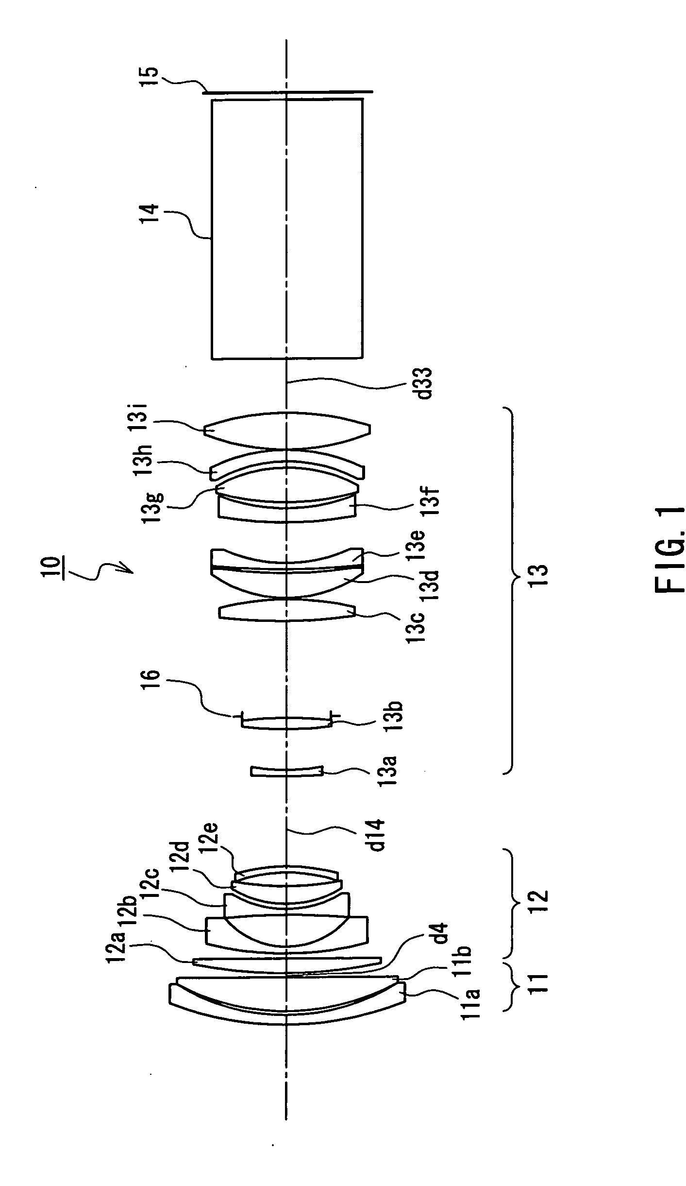
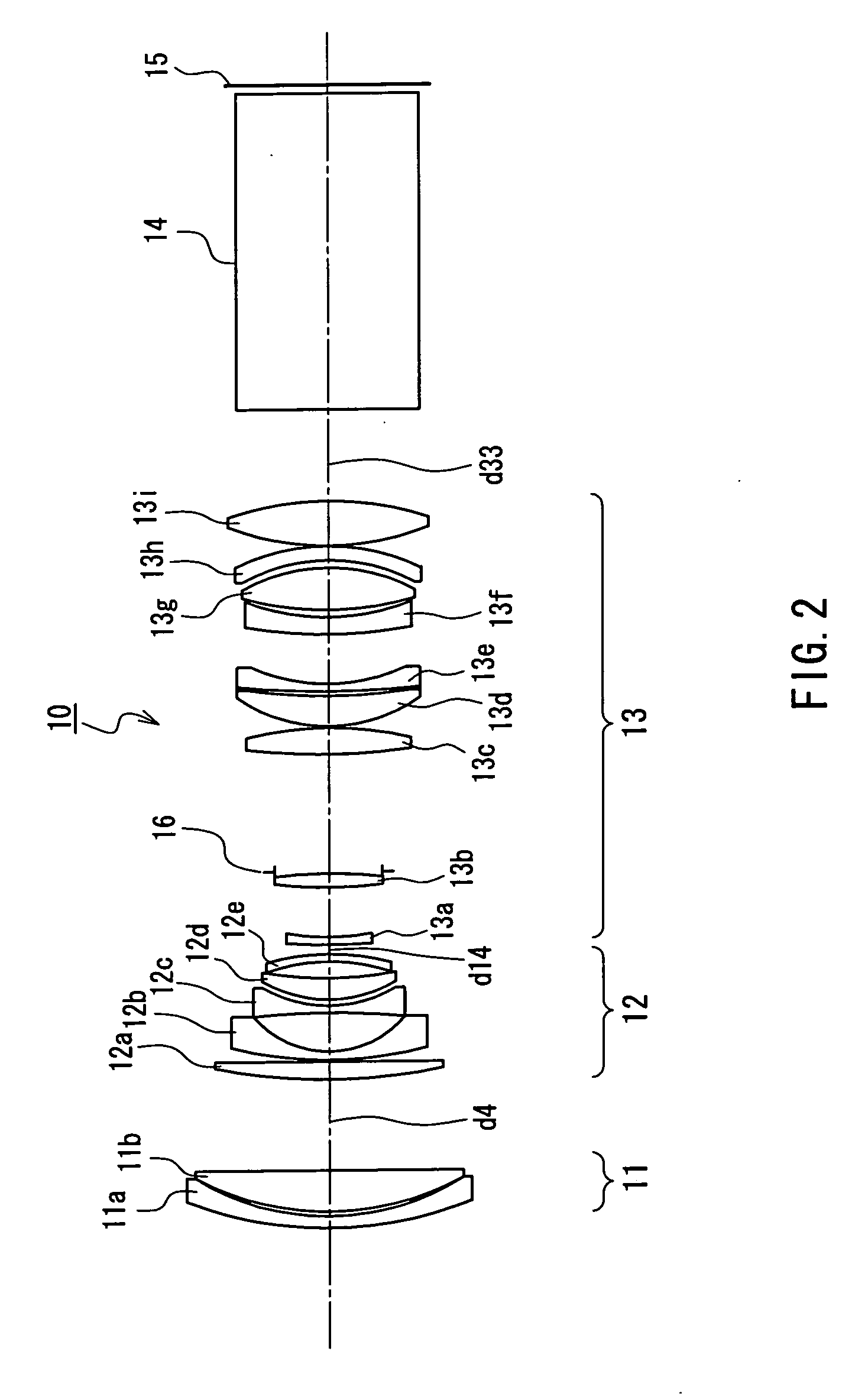
[0130]FIG. 1 shows a view of a configuration of the wide angle end of a zoom lens according to Embodiment 1 of the present invention. FIG. 2 shows a view of a configuration of the telephoto end of the zoom lens shown in FIG. 1. A zoom lens 10 shown in FIG. 1 is provided with a first lens group 11 that has positive refractive power, a second lens group 12 that has negative refractive power, and a third lens group 13 that has positive refractive power, in the order as seen from the side with the longer conjugate distance. Numeral 14 denotes a glass block such as a prism. Numeral 15 denotes an image surface, and in the case of an image-taking system denotes film or CCDs, and in the case of a projection device, it denotes LCDs, for example, which are spatial modulating elements. In the figure, the side with the longer conjugate distance is the side that is opposite the image surface 15.

[0131] When changing magnification from the wide angle end (FIG. 1) to the telephoto end (FIG. 2), th...

working example 1

[0167] Working Example 1 according to Embodiment 1 is described below. The lens configuration of Working Example 1 is the same as the configuration in FIG. 1 and FIG. 2, and is a design example in which FNO=2.5 at the wide angle end, focal length f=37.08 and a half angle of view is 24.2°. The values of the above noted Expressions (1) to (12) in Working Example 1 are as follows:

f2g / f2top=−0.22   Expression (1)

frear / f2top=0.33   Expression (2)

(1 / f1 / abe1) / (1 / frear)=−0.01   Expression (3)

nd11=1.78472   Expression (4)

nd4=1.7725   Expression (5)

vd4=49.62   Expression (6)

f4r / bfw=1.08   Expression (7)

bfw / fw=2.07   Expression (8)

fw / f1g=0.16   Expression (9)

fw / f2g=−0.78   Expression (10)

fw / f3g=0.59   Expression (11)

|(DG1−DG3) / fw|=0.11   Expression (12)

[0168] Next, specific figures are shown in Table 1, and zoom data is shown in Table 2. In Table 1, ri (mm) is the radius of curvature of the lens surface, di (mm) is the lens thickness or the interval between lenses, ni is the refrac...

embodiment 2

[0171]FIG. 5 shows a view of a configuration of the wide angle end of a zoom lens according to Embodiment 2 of the present invention. FIG.6 shows a view of a configuration of the telephoto end of the zoom lens shown in FIG. 5. A zoom lens 20 shown in FIG. 5 is provided with a first lens group 21 that has positive refractive power, a second lens group 22 that has negative refractive power, and a third lens group 23 that has positive refractive power, in the order as seen from the side with the longer conjugate distance. The glass block 14, the image surface 15 and the aperture stop 16 are configured in the same way as in FIG. 1 and are provided with the same symbols, so their description is hereby omitted. In this drawing also, the side having the longer conjugate distance is the side opposite the image surface 15.

[0172] When changing magnification from the wide angle end (FIG. 5) to the telephoto end (FIG. 6), the first lens group 21 and the third lens group 23 move to the side hav...


PUM


Abstract

The present invention includes three or more lens groups. These are arranged in the order of a first lens group (11) that has positive refractive power and a second lens group (12) that has negative refractive power, as seen from the side having the longer conjugate distance, wherein a first lens (12a) of the lenses of the second lens group (12), as seen from the side having the longer conjugate distance, has positive refractive power. Thus, it is possible to suppress distortion aberration to a small value.

Description

TECHNICAL FIELD [0001] The present invention relates to zoom lenses, and particularly relates to zoom lenses used in devices such as projectors for enlarging and projecting images, which are converted by spatial optical modulating elements, onto a screen. BACKGROUND ART [0002] In projectors that use reflecting-type spatial modulating elements for the three primary colors red, green and blue, prisms for guiding the illuminating light and prisms for combining colors are disposed between the projecting lens and the spatial modulating elements. Because of this, the projecting lens requires a long back focus. Since spectral characteristics of prisms for combining colors are dependent on the incident angle, it is necessary to have an optical system in which the pupil on the shorter side conjugate distance is a sufficient distance from the spatial modulating elements, that is to say, it is necessary to have telecentricity. [0003] For a forward convex group four-group zoom lens in which the...

Claims


Application Information

Patent Timeline
Patent Type & Authority Applications(United States)
IPC IPC(8): G02B15/14G02B15/16G02B15/173
CPCG02B15/173G02B15/161G02B15/142G02B15/143105
Inventor KIMURA, SYUNSUKETAKAHASHI, MASAYUKIYAMAMOTO, YOSHIHARU
Owner PANASONIC CORP
Learn More