
Controlling lens shape in a microlens array

a microlens array and microlens technology, applied in the field of microlens arrays, can solve the problems of large amount of incident light not being efficiently directed onto the photosensor, yellowing, heat instability, etc., and achieve the effect of modifying the melting response of the microlens material

Active Publication Date: 2006-02-02
APTINA IMAGING CORP
View PDF12 Cites 238 Cited by
  • Summary
  • Abstract
  • Description
  • Claims
  • Application Information

AI Technical Summary

Benefits of technology

"The present invention controls the shape of microlenses in an array by using patterned bleaching of the microlens material prior to a reflow process. This results in lenses with controlled focal characteristics. The array can include microlenses with identically-patterned focal characteristics or varying focal characteristics. The technical effect is the ability to control the shape of microlenses in an array, which can improve the overall performance of the array."

Problems solved by technology

The photoactive material is believed to be responsible for some yellowing, transmissivity loss, and heat instability.
In addition, despite the use of microlens arrays, a large amount of incident light is not directed efficiently onto the photosensors due to the geometry of the microlens array.
Due to size constraints, the camera lens is often mounted in close proximity to the imager.

Method used


Image

  • Controlling lens shape in a microlens array
  • Controlling lens shape in a microlens array
  • Controlling lens shape in a microlens array

Examples


Embodiment Construction

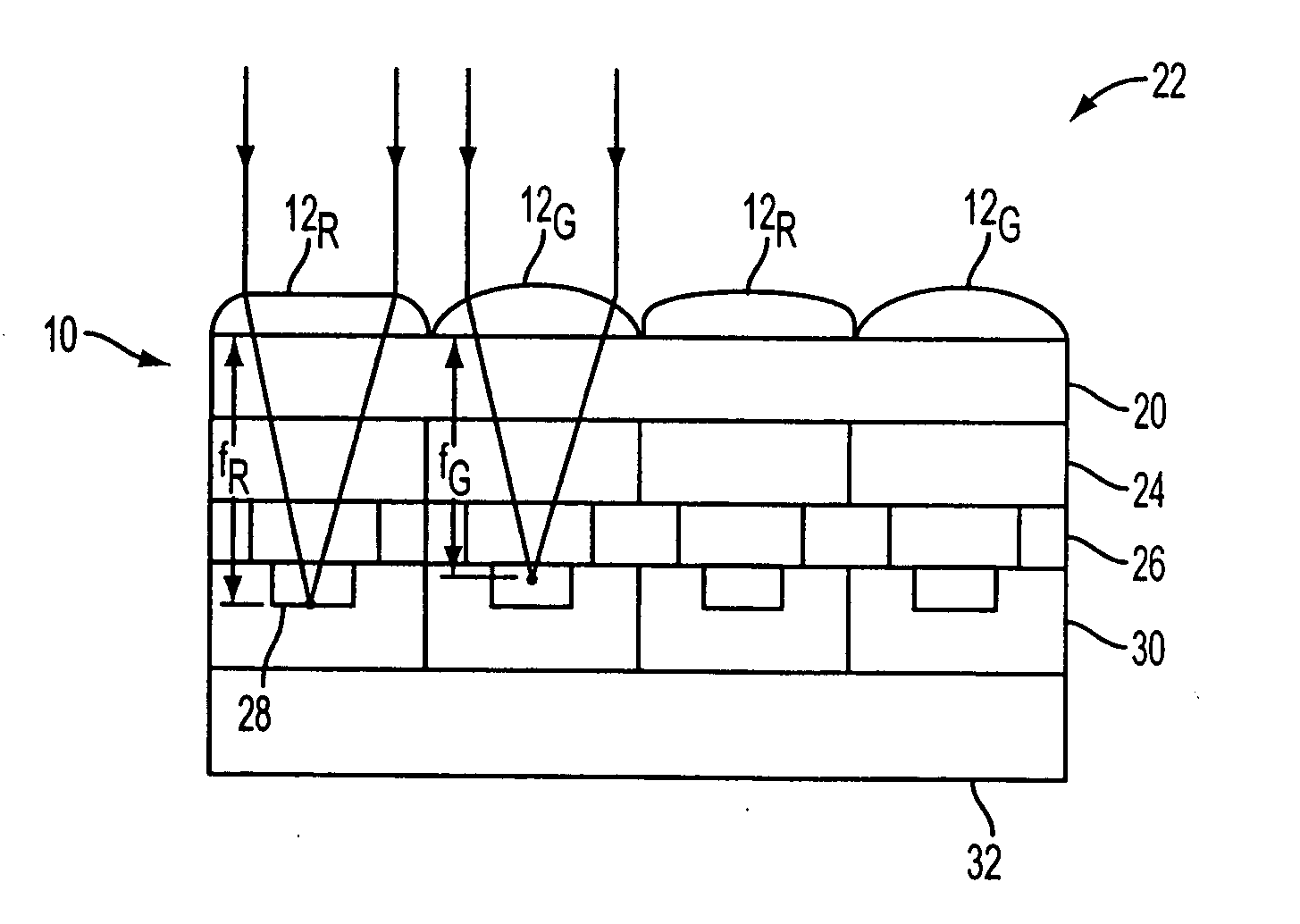
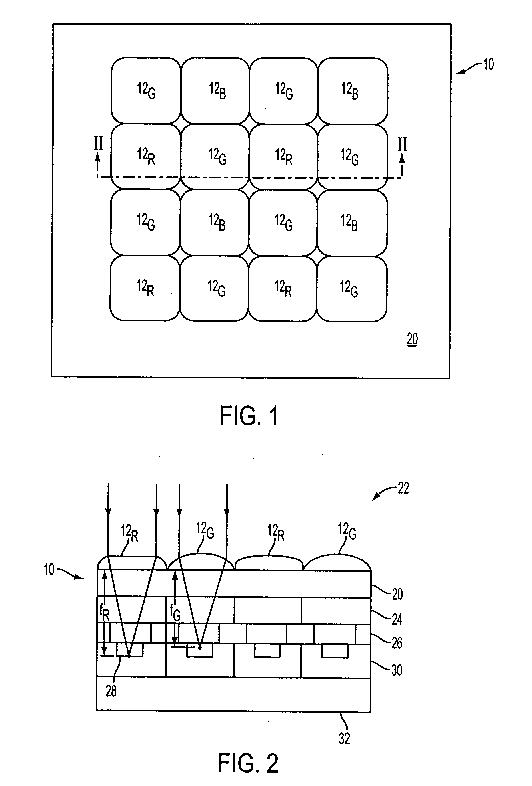
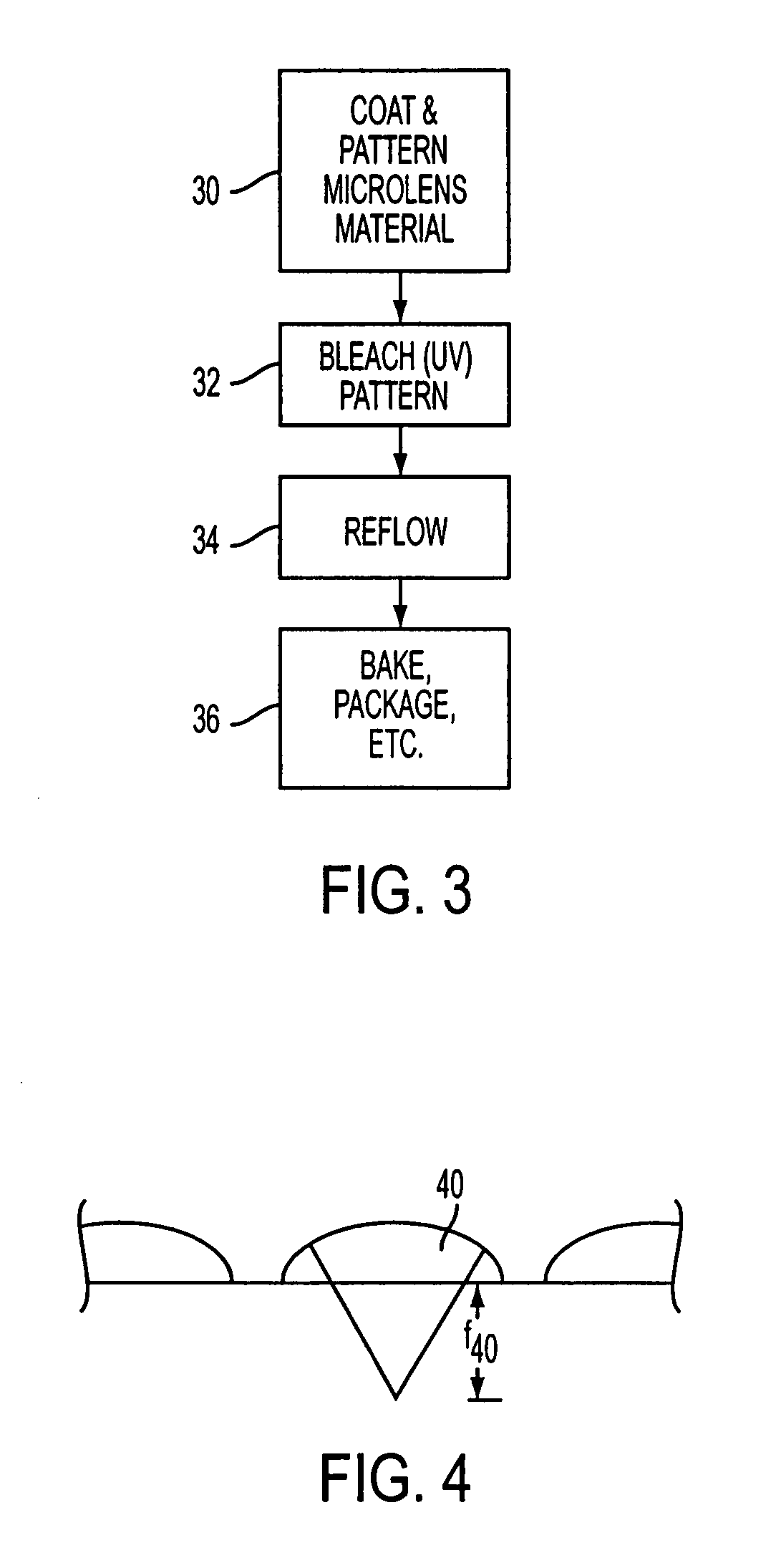
[0036] In the following detailed description, reference is made to the accompanying drawings, which form a part hereof and show by way of illustration specific embodiments in which the invention may be practiced. These embodiments are described in sufficient detail to enable those skilled in the art to practice the invention, and it is to be understood that other embodiments may be utilized, and that structural, logical, and electrical changes may be made without departing from the spirit and scope of the present invention. The progression of processing steps described is exemplary of embodiments of the invention; however, the sequence of steps is not limited to that set forth herein and may be changed as is known in the art, with the exception of steps necessarily occurring in a certain order.

[0037] The terms “wafer” or “substrate,” as used herein, are to be understood as including silicon, silicon-on-insulator (SOI), or silicon-on-sapphire (SOS) technology, doped and undoped semi...


PUM


Abstract

A semi-conductor based imager includes a microlens array having microlenses with modified focal characteristics. The microlenses are made of a microlens material, the melting properties of which are selectively modified to obtain different shapes after a reflow process. Selected microlenses, or portions of each microlens, are modified, by exposure to ultraviolet light, for example, to control the microlens shape produced by reflow melting. Controlling the microlens shape allows for modification of the focal characteristics of selected microlenses in the microlens array.

Description

FIELD OF THE INVENTION [0001] The present invention relates generally to a microlens array for use in a solid-state image sensor and in particular to a microlens array and manufacturing process in which the shape of the microlenses across the array is controlled using patterned exposure to radiation. BACKGROUND OF THE INVENTION [0002] Solid-state image sensors, also known as imagers, were developed in the late 1960s and early 1970s primarily for television image acquisition, transmission, and display. An imager absorbs incident radiation of a particular wavelength (such as optical photons, x-rays, or the like) and generates an electrical signal corresponding to the absorbed radiation. There are a number of different types of semiconductor-based imagers, including charge coupled devices (CCDs), photodiode arrays, charge injection devices (CIDs), hybrid focal plane arrays, and complementary metal oxide semiconductor (CMOS) imagers. Current applications of solid-state imagers include c...

Claims


Application Information

Patent Timeline
Patent Type & Authority Applications(United States)
IPC IPC(8): G02B27/10
CPCG02B3/0018G02B3/0043G02B3/005G02B3/0056G02B27/1013H01L27/14685G02B27/123H01L27/14603H01L27/14625H01L27/14627G02B27/1073
Inventor BOETTIGER, ULRICH C.LI, JIN
Owner APTINA IMAGING CORP
Learn More