
Method to determine position and orientation of the axis of a dental implant disposed directly in the mouth of the patient as well as a mounting piece

Inactive Publication Date: 2006-01-26
SIRONA DENTAL SYSTEMS
View PDF6 Cites 70 Cited by
  • Summary
  • Abstract
  • Description
  • Claims
  • Application Information

AI Technical Summary

Benefits of technology

[0014] Measurement data is analyzed to determine the position and orientation of a shape or geometry to be measured during the method of detecting the position and orientation of the axis of a dental implant disposed directly in the patient's mouth whereby said measurement data is acquired through optical measurement of the clinical situation of the implant in the patient's mouth by means of a suitable method, i.e. image processing. A first shape to be measured is applied to the implant whereby said shape is formed in such a manner that a conclusion can be made about the position and orientation of the implant. The relative position and orientation of the axis of the dental implant and the optical axis of the measurement is determined by the position of the first shape to be measured, and the position and orientation of the implant itself is determined through said shape. The advantage is in the fact that the clinical situation is detected directly in the patient's mouth so that manufacturing of a model is no longer necessary.
[0031] According to a further development of the invention, the surfaces of the sections have a high backscatter coefficient with a Lambert scattering distribution in the invisible as well as in near infrared range of the spectrum. The surface may be coated thereby. An equalizing device movable relative to the extension is advantageously provided which circumferentially surrounds the mounting piece and which is provided with a contact surface to rest against the gingiva surrounding the tooth restoration. The place to be measured can thus be kept free from blood and saliva. In addition, the equalizing piece can be considered a substitute model for the shape of the gingiva.
[0033] The equalizing device may thereby be adjustable in its orientation and may be provided with an identification marking making determination of the orientation possible.

Problems solved by technology

The problem is additionally compounded in that toothless jawbones degenerate after a short time and these distances are further enlarged.
It is difficult therefore to keep the implant head dry to such a degree that it can be measured directly in the patient's mouth.
This results in geometric designs of the implant head which are difficult to measure with the required accuracy by means of the traditional intraoral measuring method.
The problem is additionally compounded through an uneven powder application.
The position and orientation of the implant is applied to the working model of the dental technician by taking impressions in a costly method.
A disadvantage is thereby that a model has to be created at first to show the position and orientation of the axis of a dental implant in the clinical situation of the jaw and to subsequently make an implant structure.
Application of the method on the patient himself is not possible.

Method used


Image

  • Method to determine position and orientation of the axis of a dental implant disposed directly in the mouth of the patient as well as a mounting piece
  • Method to determine position and orientation of the axis of a dental implant disposed directly in the mouth of the patient as well as a mounting piece
  • Method to determine position and orientation of the axis of a dental implant disposed directly in the mouth of the patient as well as a mounting piece

Examples


Embodiment Construction

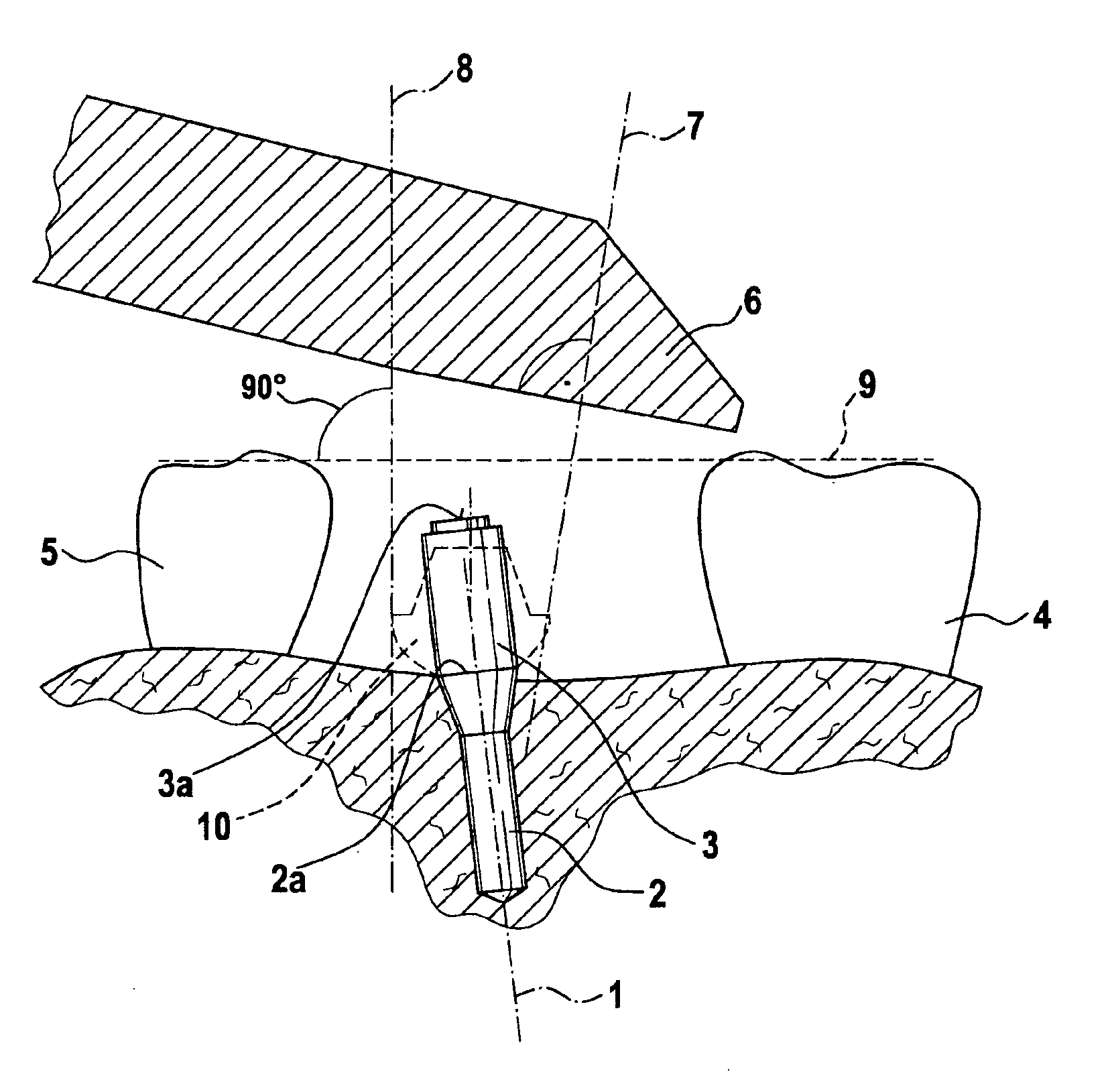
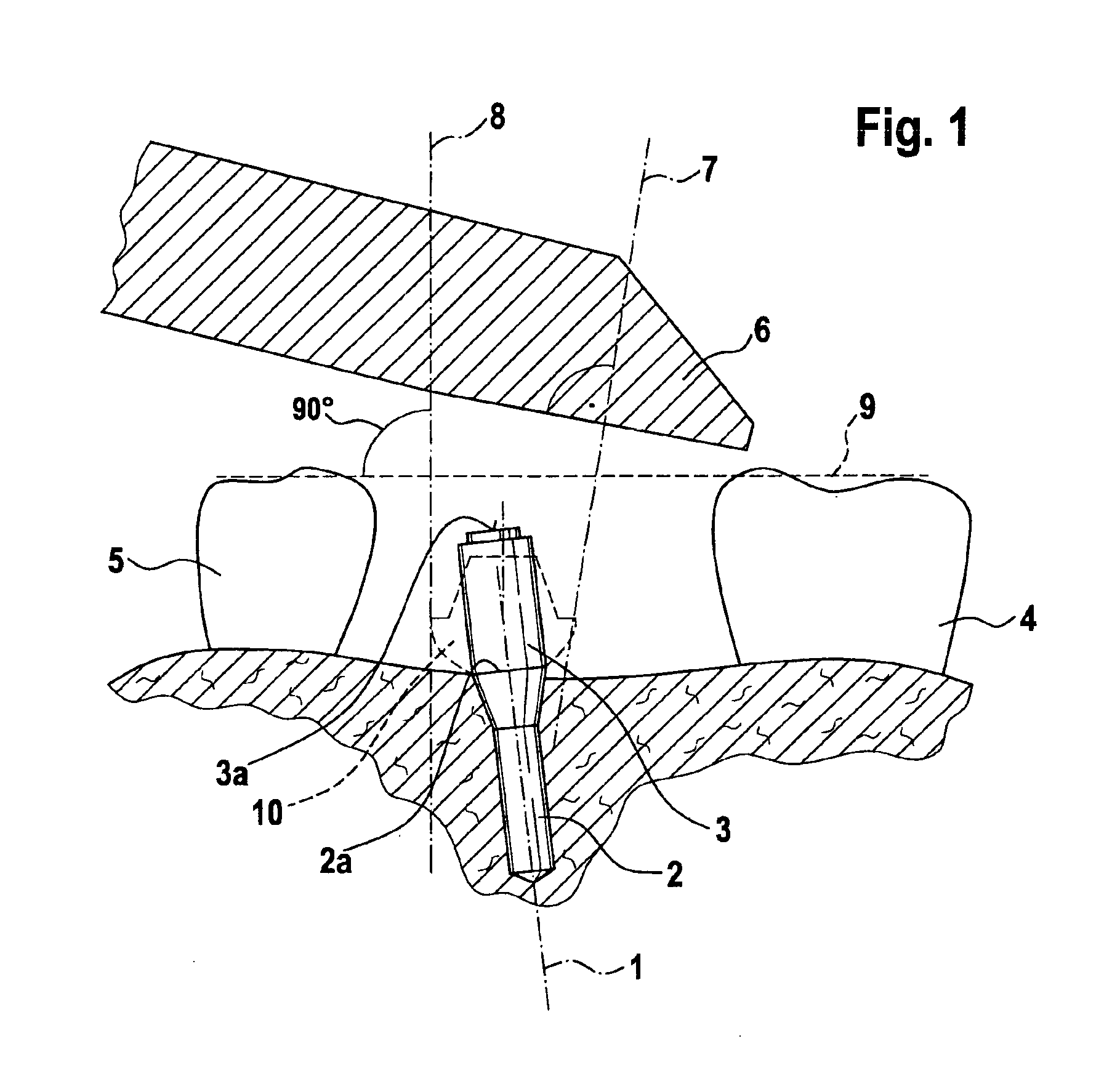
[0044] The method to detect the position and orientation of axis 1 of a dental implant 2 is explained with the aid of FIG. 1. At first, a measuring unit 3 with a first shape to be measured 3a is placed on the implant 2 disposed directly in the patient's mouth. The clinical situation, made up by the implant 2 and the existing neighboring teeth 4, 5, are optically measured, i.e. with a measuring camera 6. Three different axes determining the direction are relevant at this point: The axis 1 of the dental implant, an optical axis 7 of the measuring camera, and axis 8 of the tooth determined with consideration of neighboring teeth and which is used as the insertion axis, for example. Axis 8 lies perpendicular to an envisioned occlusion plane 9 in case where the neighboring teeth 4, 5 are molars.

[0045] Known characteristics of the tooth to be replaced can be obtained from a dental library, for example, to determine the tooth axis 8 as an addition to the system of the invention.

[0046] Th...


PUM


Abstract

A method for determining the position and orientation of the axis of a dental implant disposed directly in the mouth of a patient wherein measurement data is obtained by measurement of the clinical situation of the implant in the patient's mouth, a first shape to be measured is applied to the implant, the shape is formed in such a manner that a conclusion can be made about the position and orientation of a connection shape of the implant, and the position and orientation of the first shape is analyzed through a suitable method. Furthermore, the relative position and orientation of the area between the axis of the dental implant and the axis of the measurement is defined through the specific position of the first shape. The position and orientation of the connection shape and of the implant itself is determined through the first shape. A mounting piece for an implant inserted in a jaw or a manipulation implant in a working model can be used thereby having a coded section and an extension whose length is coded in the section.

Description

BACKGROUND OF THE INVENTION [0001] The invention relates to the field of prosthetic medical care with dental implants, and particularly to the practical arrangement of measurements, construction and production of suprastructures with the assistance of CAD / CAM systems. [0002] Prosthetic medical care with dental implants is currently a task that is performed by the dentist together with his dental laboratory. The upper edge of an enossal dental implant lies typically near the top of the jawbone in a flush manner. The difference in height between the implant head and the occlusion plane of the teeth neighboring the implant can be to such a degree that the two structures can no longer be measured simultaneously with optical measuring systems based on the limited depth-of-focus, especially in the region of the incisors or the premolar region. The problem is additionally compounded in that toothless jawbones degenerate after a short time and these distances are further enlarged. [0003] Th...

Claims


Application Information

Patent Timeline
IPC IPC(8): A61C8/00A61C19/04
CPCA61C8/00A61C8/0001A61C13/0004A61C9/0053G16H20/40
Inventor SALIGER, GUNTERORTH, ULRICHTECKENTRUP, STEFFENPIEPER, REINHARD
Owner SIRONA DENTAL SYSTEMS
Learn More