Field emission lamp

a field emission lamp and emission field technology, applied in the field of lamps, can solve the problems of mercury vapor emission and subsequent remission, mercury vapor toxic to humans and the environment, and each encapsulation procedure is complicated and time-consuming, so as to reduce the cost of field emission lamps, improve the production rate, and simplify the encapsulation procedure

Active Publication Date: 2006-01-26
TSINGHUA UNIV +1
View PDF8 Cites 12 Cited by
  • Summary
  • Abstract
  • Description
  • Claims
  • Application Information

AI Technical Summary

Benefits of technology

[0009] Compared with a conventional field emission lamp, the field emission lamp of the preferred embodiment has only one end that needs to be encapsulated. This effectively simplifies the encapsulation procedure during the manufacturing process, thereby enhancing a production rate and reducing the cost of the field emission lamp.

Problems solved by technology

This causes excitation of the mercury vapor and subsequent remission.
However, the mercury vapor is toxic to humans and environmentally unsafe.
However, the field emission lamp 20 has the two ends that need to be encapsulated, and each encapsulation procedure is complicated and time-consuming.
This means that the field emission lamp has a relatively high cost.

Method used


Image

  • Field emission lamp
  • Field emission lamp

Examples


Embodiment Construction

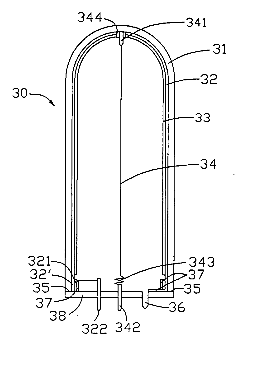
[0013] Reference will now be made to FIG. 1 to describe preferred embodiments of the present invention in detail.

[0014] A field emission lamp 30 includes: an enclosure of the lamp 30 like a tube 31 having a closed end (not labeled) and an open end (not labeled); a board-like encapsulation part 38 mated with the open end of the tube 31; an anode part 32 having a layer-like shape formed on an inner surface (not labeled) of the tube 31; a fluorescence layer 33 formed on the anode layer 32; a cathode down-lead pole 342 located at the encapsulation board 38 and protruding from opposite main surfaces (not labeled) of the encapsulation board 38; a cathode fixing pole 341 located at the closed end of the tube 31; a cathode part 34 with a filament shape having a carbon nanotube layer (not shown) formed on a surface (not labeled) thereof, and being fixed between the cathode down-lead pole 342 and the cathode fixing pole 341; an anode down-lead ring 321 located at the anode layer 32 near the ...


PUM


Abstract

A field emission lamp (30) includes a tube (31) having a closed end and an open end, an encapsulation board (38) mated with the open end, an anode layer (32) formed on an inner surface, a fluorescence layer (33) formed on the anode layer, a cathode down-lead pole (342) located at the encapsulation board, a cathode fixing pole (341) located at the closed end, a cathode filament (34) having a carbon nanotube layer formed on a surface thereof fixed between the cathode down-lead pole and the cathode fixing pole, an anode down-lead ring (321) located at the anode layer near the open end, and an anode down-lead pole (322) located at the encapsulation board and electrically connected with the anode down-lead ring. The field emission lamp has a simple structure, thereby having an enhanced production rate and a reduced cost.

Description

BACKGROUND OF THE INVENTION [0001] The invention relates generally to lamps, and more particularly to a field emission lamp. [0002] Lamps are virtual necessities in modern daily living, and a conventional luminescent lamp generally adopts mercury vapor. In use, electrons are accelerated by an electric field so that the accelerated electrons collide with the mercury vapor. This causes excitation of the mercury vapor and subsequent remission. The remission process causes radiation of ultraviolet rays. The ultraviolet rays irradiate a fluorescent material of the lamp, whereby the ultraviolet rays are converted into visible light. [0003] However, the mercury vapor is toxic to humans and environmentally unsafe. Therefore in recent years, field emission lamps which adopt carbon nanotubes as emitters have been manufactured to replace conventional luminescent lamps. [0004] Referring to FIG. 2, a field emission lamp as disclosed in an article entitled “A Full Sealed Luminescent Tube Based on...

Claims


Application Information

Patent Timeline
Patent Type & Authority Applications(United States)
IPC IPC(8): H01J1/62H01J63/04
CPCH01J63/06B82Y10/00
Inventor WEI, YANGLIU, PENGSHENG, LEI-MEILIU, LIANGHU, ZHAO-FUGUO, CAI-LINCHEN, PI-JINFAN, SHOU-SHAN
Owner TSINGHUA UNIV
Why Eureka
Try Eureka