Thermoelectric effect apparatus, energy direct conversion system , and energy conversion system

Inactive Publication Date: 2006-01-26
MEIDENSHA ELECTRIC MFG CO LTD +1
View PDF6 Cites 14 Cited by
  • Summary
  • Abstract
  • Description
  • Claims
  • Application Information

AI Technical Summary

Benefits of technology

[0012] A system that can obtain an energy source satisfying the purpose needs to have a thermally open system and a circulating type form. More specifically, the invention provides an electric circuit system which can conduct thermal energy transfer by a Peltier device between areas apart from a given distance, directly convert thermal energy to electrical potential energy by a Seebeck device, and utilize the electrolysis of electrolyte solutions and water to convert electrical potential energy to chemical potential energy to easily store, accumulate and transfer energy.
[0013] For example, the system can effectively use and reuse thermal energy in the natural world with no use of fossil fuels, convert the thermal energy to electric energy for use as electric power, convert it to chemical energy, and thus construct an open energy recycling system. Therefore, a direct energy conversion system can be provided which can reduce global warming and have little environment load accompanied by pollution.

Problems solved by technology

However, a direct power generator device like the Seebeck device as described above cannot obtain sufficient electric power, and has limitations for use as a small-scale energy source.
Therefore, in reality, the form of applications has also limitations.
More specifically, in the Seebeck device, the heating module thermally, mutually interferes with the cooling module, and in the Peltier device, the heat absorbing module thermally, mutually interferes with the heat generating module.
Therefore, when the Peltier device and the Seebeck device are used to construct large-scale energy conversion facilities, it is unrealistic because physical limitations are imposed on installation locations for the facilities.
This is a great problem essential for energy development in future.

Method used


Image

  • Thermoelectric effect apparatus, energy direct conversion system , and energy conversion system
  • Thermoelectric effect apparatus, energy direct conversion system , and energy conversion system
  • Thermoelectric effect apparatus, energy direct conversion system , and energy conversion system

Examples


first embodiment

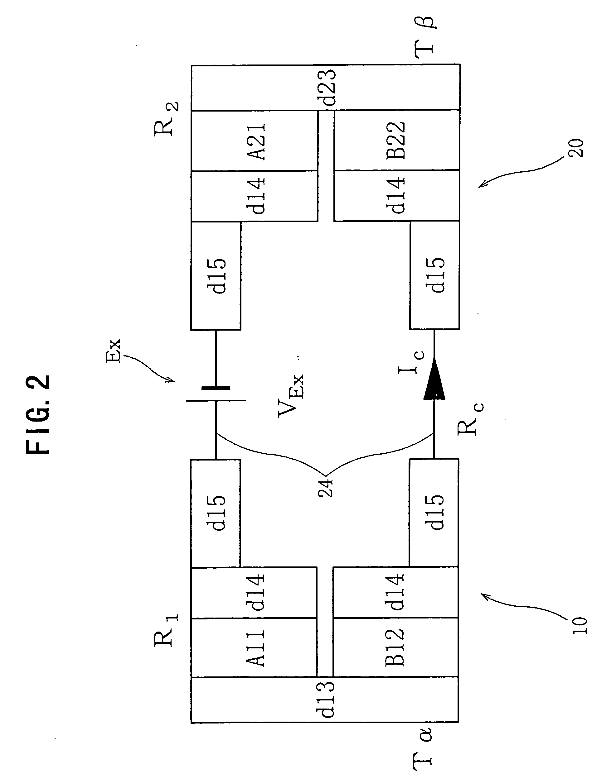
[0053]FIG. 2 relates to a thermoelectric apparatus of a first embodiment, and is a schematic circuit diagram for describing a pair of Peltier effect heat transfer circuit systems that can freely set a space between two thermoelectric transducers. In addition, in each of symbols shown in FIG. 2, R1 and R2 denote resistance of conductive members on the heat absorption side and the heat generation side (or on the high temperature side and the low temperature side), IC denotes circuit current, RC denotes circuit resistance at a connecting conductive member, and VEX denotes external power source voltage. Each of the symbols is the same in embodiments and examples below.

[0054] As shown in FIG. 2, a first conductive member A11 and a second conductive member B12 having different Seebeck coefficients are joined to each other through a joining member d13 formed of a material of excellent thermal conductivity and electrical conductivity (such as copper, gold, platinum, and aluminum) to form a...

second embodiment

[0068] The external direct-current power supply EX was removed from the Peltier effect circuit shown in FIG. 2 of the first embodiment, and the both ends of the circuit, that is, the joining member d13 of the first thermoelectric transducer 10 and the joining member d23 of the second thermoelectric transducer 20 were heated and cooled to provide a temperature difference about a temperature of 80° C. It could be confirmed that an electromotive force of 0.2 mv was generated at the terminal where the power source EX had been removed. Furthermore, it could also be confirmed that the Seebeck effect was not dissipated and was kept in the configuration in which the first thermoelectric transducer 10 of the heating side was separated from the second thermoelectric transducer 20 of the cooling side.

[0069]FIG. 7 relates to a second embodiment, and is a schematic circuit diagram for describing a pair of direct conversion circuit systems from thermal energy to electric energy by the Seebeck ef...

third embodiment

[0076] In a third embodiment, based on the basic technical concept of the invention, specific configurations for achieving an object of the invention (for example, specific examples of the configurations shown in the first and second embodiments) will be described.

[0077]FIG. 8 is a schematic circuit diagram illustrating a self-driven heat transfer system for describing a direct energy conversion system using a thermoelectric apparatus (for example, the thermoelectric apparatus of the first embodiment) in the third embodiment. In addition, in FIG. 8 (and FIGS. 10 to 16 described later), Vs denotes voltage output, RC1 and RC2 denote circuit resistance, and IC denotes circuit current. Furthermore, a symbol 30 denotes a thermoelectric transducer as similar to the first thermoelectric transducer 10 and the second thermoelectric transducer 20 shown in FIG. 7. Moreover, Is denotes an insulating material having excellent thermal conductivity and insulation properties (for example, silicone...


PUM


Abstract

A self-driven direct energy conversion system is to be provided which can suppress global warming using a heat generation apparatus that can obtain a circulating type and open system energy source utilizing exhaustless, reusable thermal energy with no pollution in the natural world. The system has a thermal energy transfer module which a Peltier effect device group is separated from a Seebeck effect device group at a given distance, an electric power generating module, and an electrolyzer module in which thermal energy transfer and electric energy conversion are conducted, and a water electrolyzer circuit artificially forms a chemical energy source of hydrogen gas and oxygen gas easily pressurized, compressed, accumulated, stored, and transferred. Thus, thermal energy, electric power, and chemical energy are utilized.

Description

BACKGROUND OF THE INVENTION [0001] 1. Field of the Invention [0002] The present invention relates to an apparatus and its system, which conduct energy interconversion or thermal energy transfer in different forms, particularly to a thermoelectric apparatus, a direct energy conversion system, and an energy conversion system, which directly convert or transfer thermal energy existing in the natural world to electric energy and chemical energy. [0003] 2. Description of the Related Art [0004] Since the invention is the invention that has been developed based on publicly known and publicly used techniques (the forms of energy use by thermoelectric transducers) without conducting related art search, the related art known by the applicant does not fall in the documented publicly known invention. Hereinafter, the forms of energy use publicly known and publicly used will be described. [0005] In the recent forms of energy use, most of them irreversibly utilize fossil fuels, nuclear power, and...

Claims


Application Information

Patent Timeline
IPC IPC(8): H01L35/32H01L35/28H02N11/00
CPCH01L35/28H10N10/10
Inventor KONDOH, YOSHIOMI
Owner MEIDENSHA ELECTRIC MFG CO LTD
Why Eureka
Try Eureka