
Anti-bunker ammunition

a technology of ammunition and ammunition, applied in the direction of ammunition projectiles, weapons, projectiles, etc., can solve the problems of reducing the effectiveness of explosive ammunition, increasing the mass of ammunition without necessarily increasing the mass of the front part, and disorganizing or fractured explosive charge during its passag

Inactive Publication Date: 2006-01-26
GIAT INDS SA
View PDF15 Cites 12 Cited by
  • Summary
  • Abstract
  • Description
  • Claims
  • Application Information

AI Technical Summary

Benefits of technology

[0010] Thus, the anti-bunker ammunition according to the invention allows the effectiveness of the splinter charge to be controlled whatever the thickness of the wall through which it passes.

Problems solved by technology

The problem with these pieces of ammunition is that, when the wall to be passed through is of great width (more than one meter), the explosive charge may be disorganized or fractured during its passage.
The effectiveness of the explosive ammunition is thus severely reduced.
However, this increases the mass of the ammunition without necessarily increasing the mass of the front part ensuring the perforation.
Furthermore, the volume available for the explosive is reduced and the effectiveness of the splinter cone may be reduced due to the over-fragmentation of the casing.
It is not possible for the radius of effectiveness of this splinter charge to be defined reliably and reproducibly since it becomes deformed after passing through a wall.

Method used


Image

  • Anti-bunker ammunition
  • Anti-bunker ammunition
  • Anti-bunker ammunition

Examples


Embodiment Construction

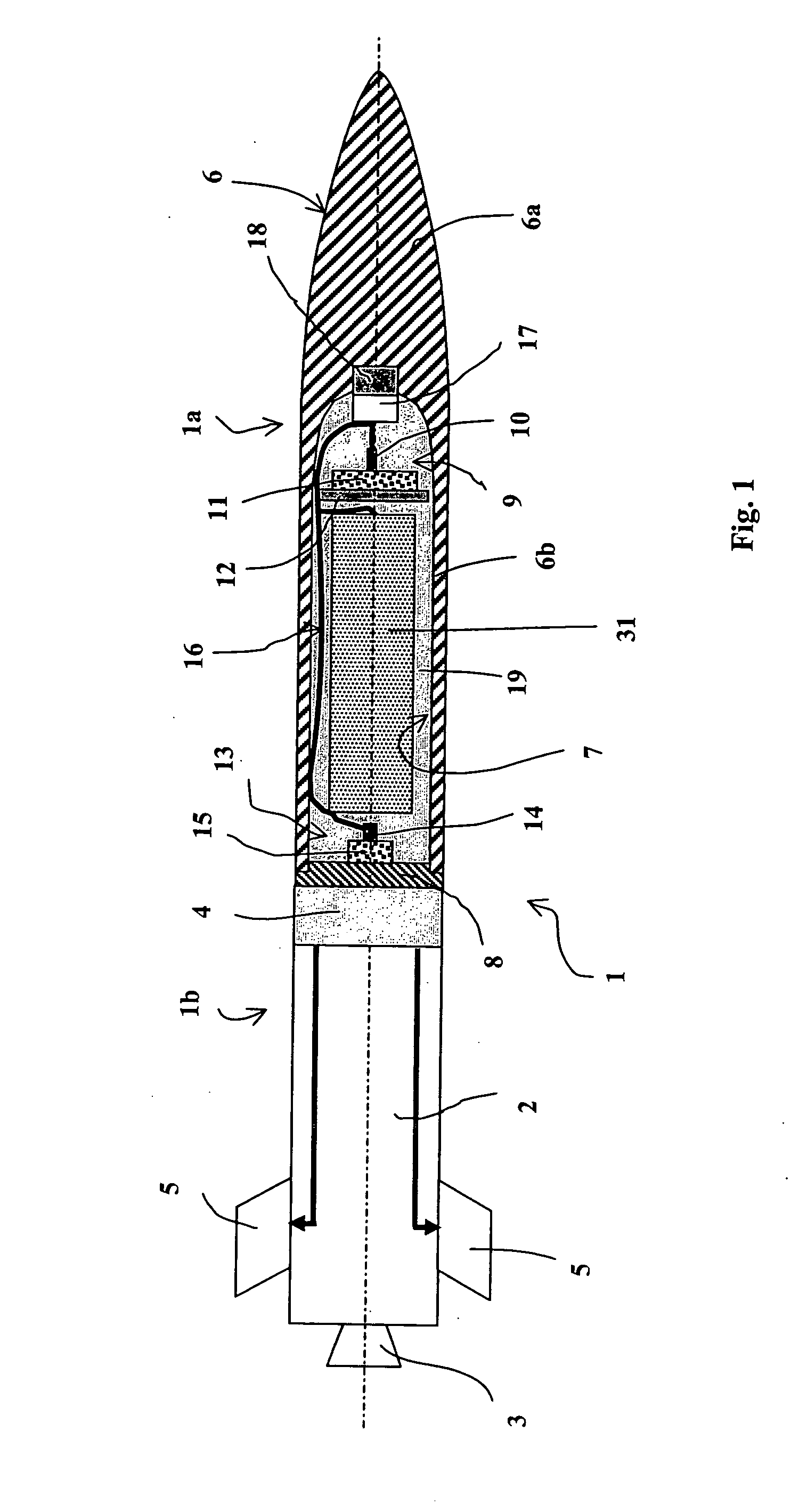
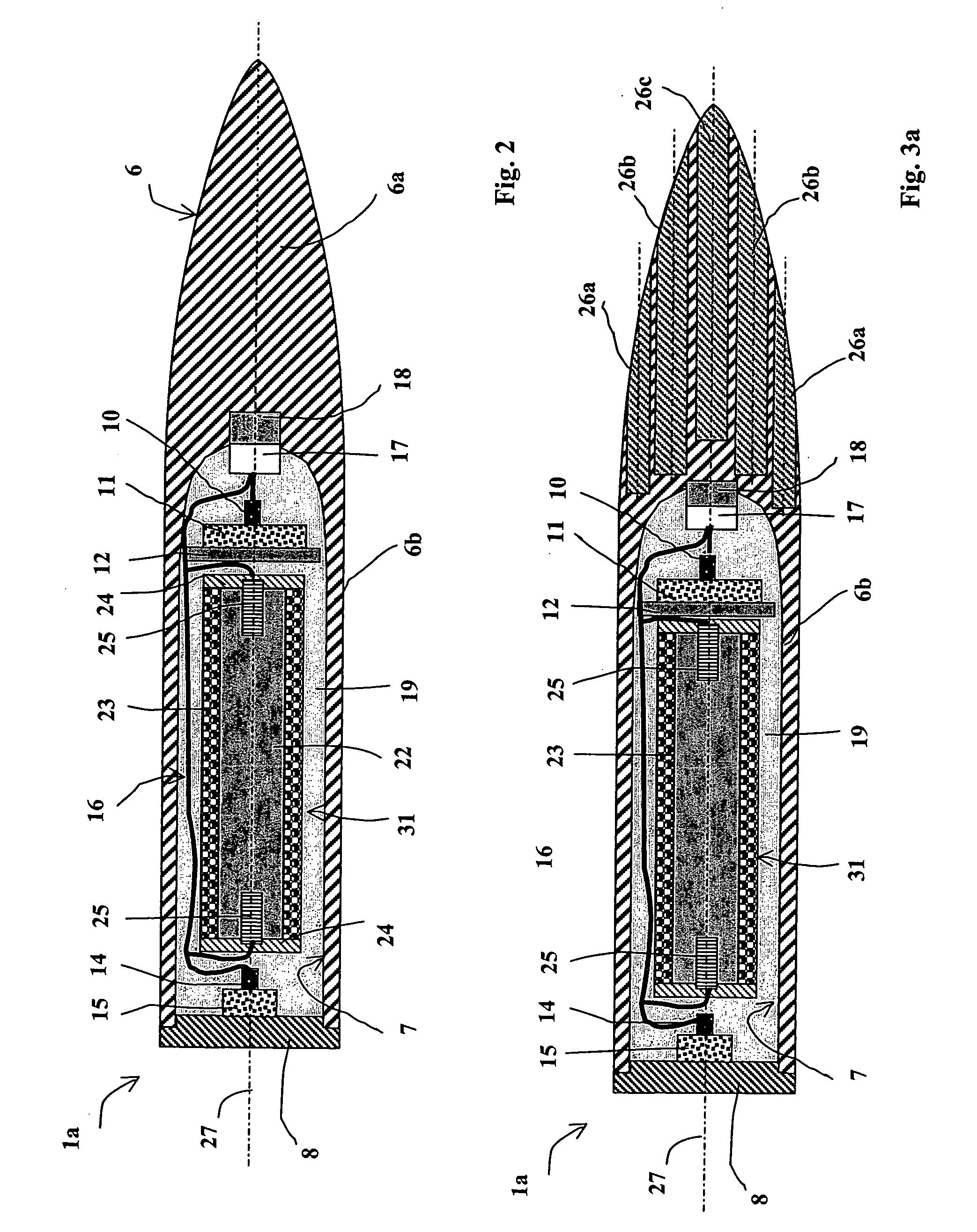
[0029] With reference to FIG. 1, an anti-bunker ammunition 1 according to one embodiment of the invention comprises a front perforating warhead 1a which here is integral with a rear part 1b comprising a propellant module 2 and an electronic guiding / piloting module 4.

[0030] The propellant module 2 is not shown here in detail. It classically encloses a gas-generating propellant charge (not shown), such gases ejected rearwards of the ammunition 1 by a nozzle 3.

[0031] The electronic guiding / piloting module 4 is also not shown in detail. It is connected to four rear piloting fins 5 formed into a cross.

[0032] The ammunition 1 thus constitutes a missile or else an air-to-ground bomb having a piloting capability to a target.

[0033] The propellant module 2 allows the projectile to be given a minimal velocity required for impact on a target, such velocity ensuring the perforation of the target. This module may thus be ignited only a few tens of meters before impact. For a concrete target o...


PUM


Abstract

The invention relates to an anti-bunker ammunition comprising a penetration body delimiting an internal cavity closed by a base characterized in that the cavity encloses at least one sub-munition, a device to eject said sub-munition as well as a device to eject the base, the sub-munition and the ejection devices being insulated from the walls of the internal cavity by shock-absorbing means.

Description

BACKGROUND OF THE INVENTION [0001] 1. Field of Invention [0002] The technical scope of the invention is that of ammunition able to destroy targets heavily protected by a wall, for example of concrete. [0003] 2. Description of the Related Art [0004] It is known, namely by patent U.S. Pat. No. 6,186,072, to define a piece of ammunition incorporating a perforating body whose inertia ensures its passage through thick protective walls. This ammunition encloses an explosive or incendiary charge that is ignited during the perforation or after perforation of the wall. [0005] The problem with these pieces of ammunition is that, when the wall to be passed through is of great width (more than one meter), the explosive charge may be disorganized or fractured during its passage. The effectiveness of the explosive ammunition is thus severely reduced. [0006] One means to improve the resistance of this ammunition is to thicken the casing surrounding the explosive. However, this increases the mass o...

Claims


Application Information

Patent Timeline
IPC IPC(8): F42B12/02F42B12/62
CPCF42B12/62
Inventor ECHES, NICOLASBOUCHAUD, DOMINIQUE
Owner GIAT INDS SA
Learn More