
Coding apparatus, coding method, coding method program, and recording medium recording the coding method program

a coding method and coding method technology, applied in signal generators with optical-mechanical scanning, color television with bandwidth reduction, etc., can solve problems such as image quality stability hindered, mpeg2 is a broadcast-oriented high-quality coding system, and is not compliant with coding systems at high compression ratios, so as to simplify the overall construction

Inactive Publication Date: 2006-01-19
SONY CORP
View PDF3 Cites 56 Cited by
  • Summary
  • Abstract
  • Description
  • Claims
  • Application Information

AI Technical Summary

Benefits of technology

[0080] The present invention has been made in consideration of the foregoing. There is a need for constructing a coding apparatus to function as a decoding apparatus and an image conversion apparatus. In such case, it is desirable to provide a coding apparatus, a coding method, a coding method program, and a recording medium recording the coding method program capable of simplifying the overall construction.
[0085] The construction of the embodiment may be applied to a coding apparatus so as to include intra prediction means for selecting an optimum prediction mode using the video data in advance for at least one GOP prior to coding by the coding means and detecting an intra prediction variable indicating a size of differential data in the optimum prediction mode; inter prediction means for selecting an optimum prediction mode using the video data in advance for at least one GOP prior to coding by the coding means and detecting an inter prediction variable indicating a size of differential data in the optimum prediction mode; difficulty calculation means for comparing a variable for the intra prediction with a variable for the inter prediction and detecting a variable indicating a size of differential data in an optimum prediction mode; and rate control means for distributing a data amount to be allocated to one GOP among pictures based on a variable indicating a size of the differential data to calculate a target code amount of each picture and providing rate control for a coding process by the coding means based on the target code amount. There may be a case of constructing the coding apparatus so as to function as a decoding apparatus and an image conversion apparatus. In such case, a variable indicating the differential data size may be replaced by a multiplied value between a quantization scale for each picture obtained by the decoding apparatus and a code amount, for example. This makes it possible to provide rate control by effectively using various information detected in decoding processes. In this manner, the construction can be simplified to ensure the function as the image conversion apparatus.
[0087] According to the embodiments of the present invention, the overall construction can be simplified when the coding apparatus may be configured to function as a decoding apparatus and an image conversion apparatus.

Problems solved by technology

However, the MPEG2 is a broadcast-oriented high quality coding system and is not compliant with coding systems at high compression ratios with less code amounts than MPEG1.
Accordingly, the image quality stability may be hindered.

Method used


Image

  • Coding apparatus, coding method, coding method program, and recording medium recording the coding method program
  • Coding apparatus, coding method, coding method program, and recording medium recording the coding method program
  • Coding apparatus, coding method, coding method program, and recording medium recording the coding method program

Examples


embodiment 1

[0105] [Embodiment 1]

[0106] (1) Construction of the Embodiment

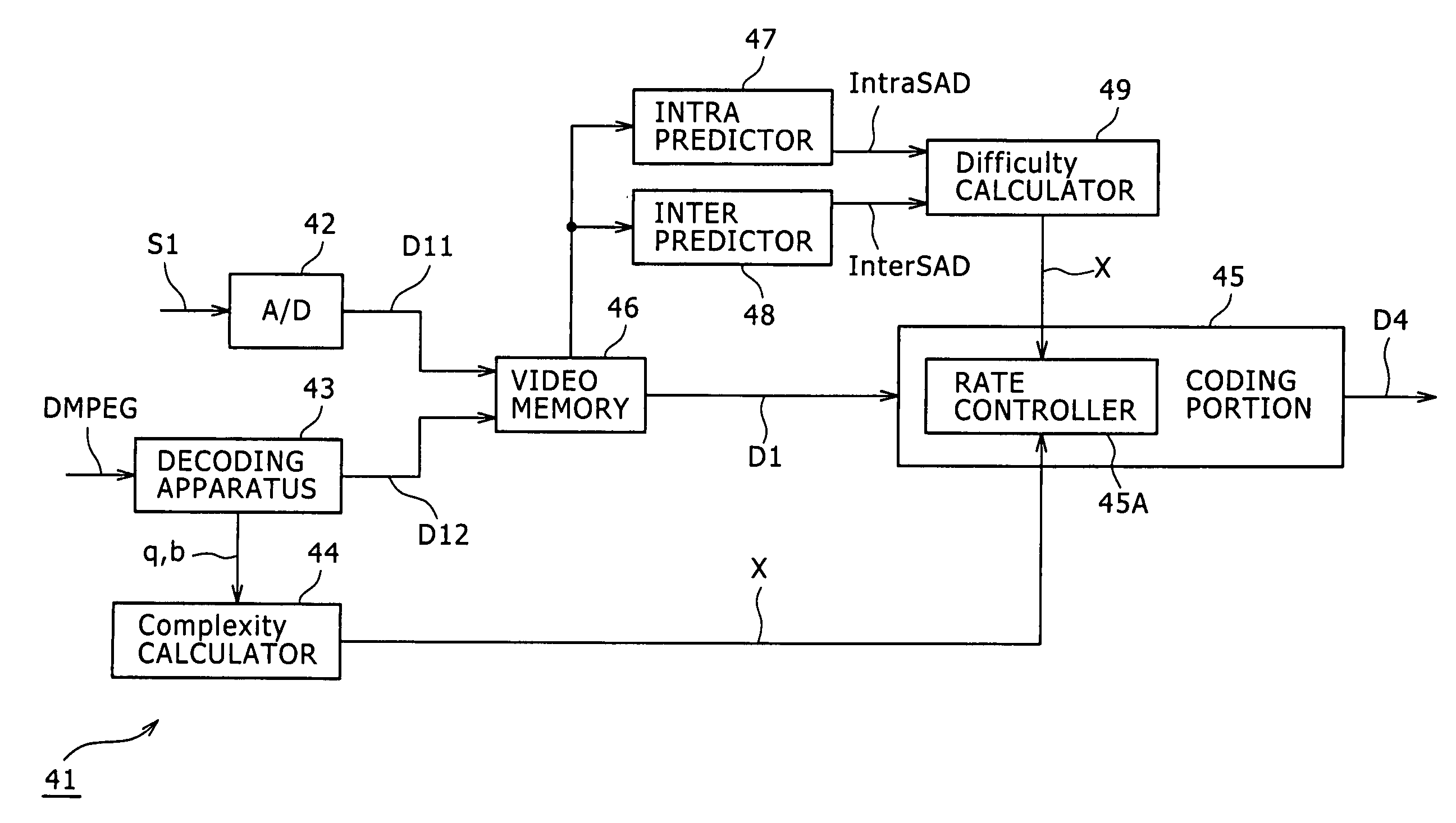
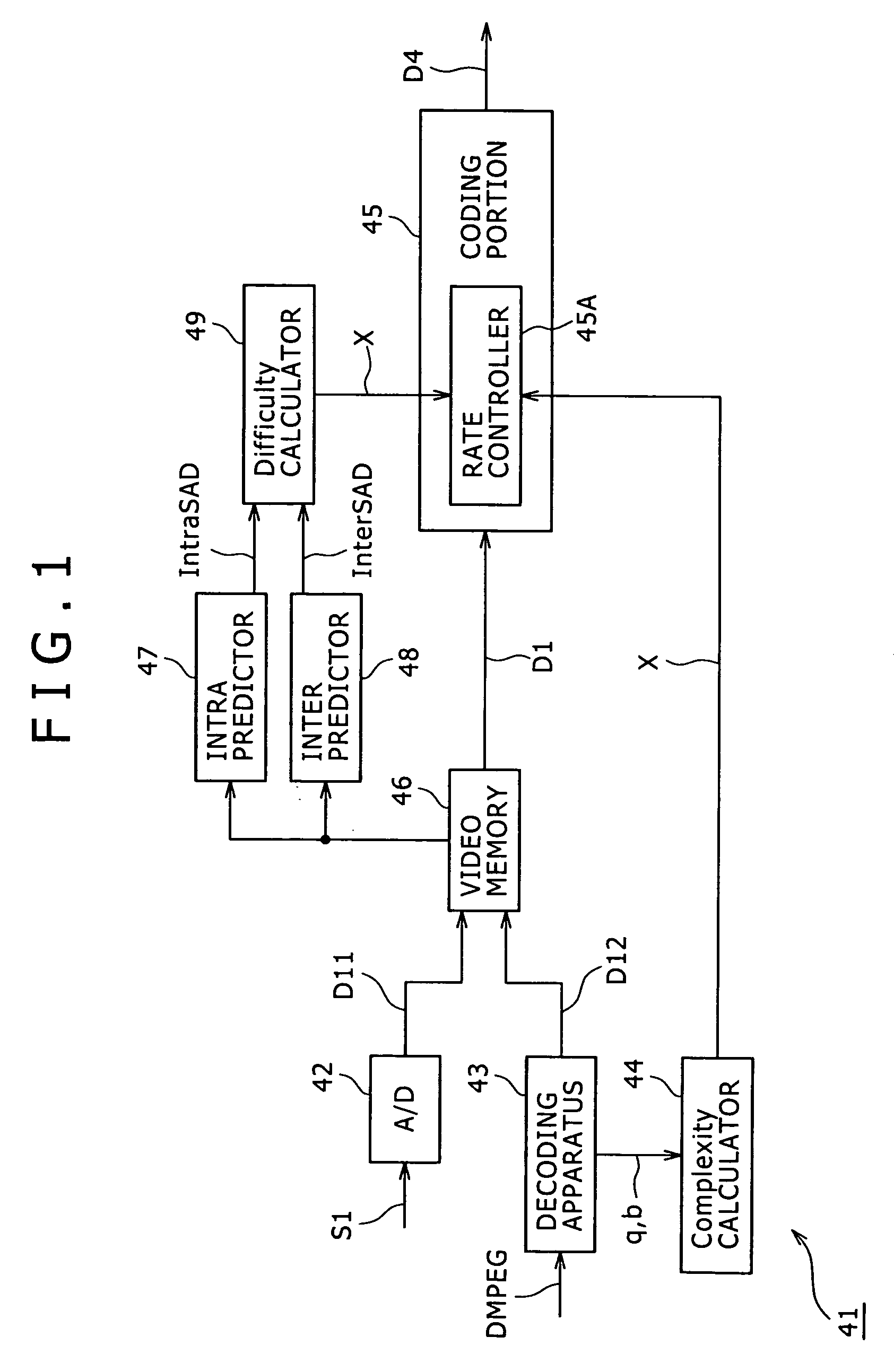
[0107]FIG. 1 is a block diagram showing a coding apparatus according to an embodiment of the present invention. For example, a DVD player or the like reproduces MPEG2 compressed coding data DMPEG. A television tuner outputs analog video signal S1. A recording and reproducing apparatus records the coded data DMPEG and the video signal S1 on recording media such as optical disks. A coding apparatus 41 is applicable to such recording and reproducing apparatus, compresses the coded data DMPEG and the video signal S1 based on the AVC, and outputs coded data D4.

[0108] In the coding apparatus 41, an A / D converter (A / D) 42 analog-digital converts the video signal S1 and outputs video data D11.

[0109] The decoding apparatus 43 is supplied with MPEG2-based coded data DMPEG, decodes the coded data DMPEG, and outputs baseband-based video data D12. In this process, the decoding apparatus 43 notifies a complexity calculator 44 of qua...

embodiment 2

[0161] [Embodiment 2]

[0162] According to this embodiment, a computer executes a coding program. In this manner, the computer provides function blocks corresponding to the blocks of the above-mentioned coding apparatus 41 with reference to embodiment 1. The computer performs processes equivalent to those of the coding apparatus 41. The coding program may be provided by being preinstalled in computers. Further, the coding program may be provided by being downloaded via networks such as the Internet. Alternatively, the coding program may be provided by being recorded on recording media. There may be available various recording media such as optical disks, magnetic optical disks, and the like.

[0163] Like this embodiment, a computer may execute the processing program to construct the function blocks similar to those of the coding apparatus 41 according to embodiment 1 for coding. Also in this case, embodiment 2 can provide the effects similar to those for embodiment 1.

embodiment 3

[0164] [Embodiment 3]

[0165] In the above-mentioned embodiments, there has been described the case of detecting variables concerning intra prediction and inter prediction using the sum of absolute differences in differential data. However, the present invention is not limited thereto. Various parameters can be widely applied as needed such as the sum of squares of differential data, for example, in stead of the sum of absolute differences in differential data.

[0166] In the above-mentioned embodiments, there has been described the case of simplifying processes in the intra prediction means and the inter prediction means for intra prediction and inter prediction in the coding means in terms of the accuracy associated with the reference image information and the motion compensation and in terms of the types of blocks associated with the prediction mode. However, the present invention is not limited thereto. When the practically sufficient throughput can be ensured, the intra prediction...


PUM


Abstract

Disclosed is an coding apparatus, an coding method, an coding method program, and a recording medium recording the coding method program. The present invention is applicable to transmission of motion pictures using satellite broadcasts, cable television, Internet, cellular phones, and the like, and recording of motion pictures on recording media such as optical disks, magnetic optical disks, flash memory, and the like, for example. In this manner, the coding apparatus can be also constructed to function as a decoding apparatus and an image conversion apparatus. An embodiment of the present invention can simplify the overall construction of such coding apparatus. An embodiment of the present invention detects an optimum prediction mode for intra prediction and inter prediction prior to a coding process. The embodiment detects variables IntraSAD, InterSAD, and (X) indicating differential data sizes according to the detected optimum prediction mode. The embodiment determines target code amounts for pictures according to the variables IntraSAD, InterSAD, and (X).

Description

CROSS REFERENCES TO RELATED APPLICATIONS [0001] The present invention contains subject matter related to Japanese Patent Application JP 2004-200255 filed in the Japanese Patent Office on Jul. 7, 2004, the entire contents of which being incorporated herein by reference. BACKGROUND OF THE INVENTION [0002] 1. Field of the Invention [0003] The present invention relates to a coding apparatus, a coding method, a coding method program, and a recording medium recording the coding method program. The present invention is applicable to transmission of motion pictures using satellite broadcasts, cable television, Internet, cellular phones, and the like, and recording of motion pictures on recording media such as optical disks, magnetic optical disks, flash memory, and the like, for example. The coding apparatus can detect an optimal prediction mode for intra prediction and inter prediction prior to a coding process. The coding apparatus can detect a variable indicating the differential data si...

Claims


Application Information

Patent Timeline
IPC IPC(8): H04B1/66H04N11/02H04N11/04H04N7/12H04N19/50H04N19/105H04N19/109H04N19/11H04N19/115H04N19/12H04N19/126H04N19/134H04N19/136H04N19/137H04N19/14H04N19/147H04N19/172H04N19/176H04N19/177H04N19/186H04N19/19H04N19/196H04N19/503H04N19/523H04N19/567H04N19/577H04N19/593H04N19/60H04N19/61H04N19/625H04N19/85H04N19/91
CPCH04N19/159H04N19/149H04N19/61H04N19/124H04N19/107H04N19/109H04N19/11
Inventor SATO, KAZUSHIZHU, YIWENYAGASAKI, YOICHI
Owner SONY CORP
Learn More