
Lighting apparatus for discharge lamp

a discharge lamp and light source technology, applied in lighting apparatus, light sources, instruments, etc., can solve the problems of discharge lamps, electromagnetic noise radiation, and difficulty in obtaining a correlation between lamp voltage and optical output, and achieve the effect of suppressing the generation of noise and optimum rising characteristics of optical outpu

Inactive Publication Date: 2006-01-19
KOITO MFG CO LTD
View PDF17 Cites 4 Cited by
  • Summary
  • Abstract
  • Description
  • Claims
  • Application Information

AI Technical Summary

Benefits of technology

[0029] An object of the invention is to realize the optimum rising characteristics of the optical output of a discharge lamp while suppressing the generation of noise in a lighting apparatus for the discharge lamp which does not contain any mercury or contains a small amount of mercury. However, the present invention may have other objects, or no objects at all without departing from its scope.
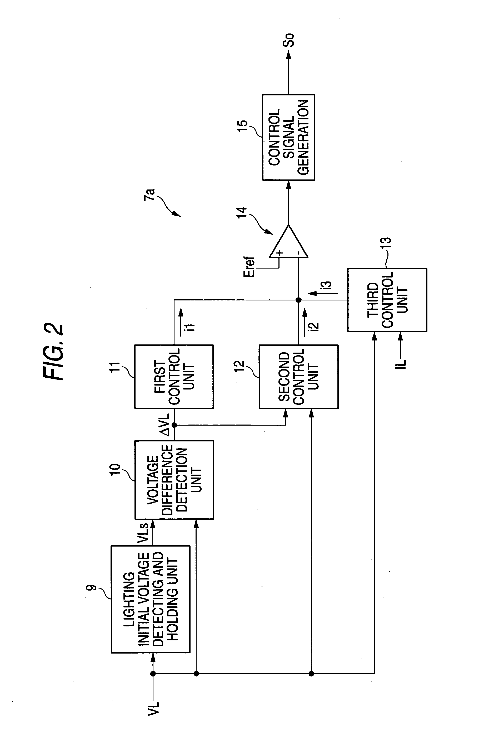
[0033] According to the invention, during the transient time period where the discharge lamp reaches the stable lighting state, the electric power control can be performed so as to suppress the radiation noise from a luminous tube and also not to cause a remarkable amount of overshoot as to the rising characteristics of the optical output for the suppression of the noise.
[0035] For example, in the configuration where the time constant circuit includes a capacitor and a plurality of resistors, the electric power during the transient time period is controlled in accordance with a first time constant at the time point where the voltage change value relating to the lamp voltage from the initial value thereof is detected to reach at least the threshold value or more, thereby suppressing the noise. Thereafter the electric power during the transient time period is controlled in accordance with a second time constant smaller than the first time constant. According to this configuration, the switching of the time constant is required to be only two steps and so the simple circuit configuration can be realized (it becomes difficult to obtain the condition for the switching timing etc. in the case of three or more stages).

Problems solved by technology

In contrast, in the discharge lamp of mercury-free type, since the change value of the lamp voltage is small during a time period from the start of the lighting to the steady lighting, it is difficult to obtain a correlation between the lamp voltage and the optical output.
In the noise generation period Tn started from the time point t3 (for example, 10 to 20 seconds after the starting of the lighting), a state of the discharge lamp is unstable and so there arise a problem that electromagnetic noise is radiated during this time period.
In the related art circuit configuration, there is a problem in that it is difficult to obtain good rising characteristics of the optical output and to suppress the influence of the electromagnetic noise.
Thus, the transient power control for the discharge lamp of mercury-free type requires a long time period from the start of the lighting to the stable state of the discharge as compared with the discharge lamp containing mercury.
As a result, when the electromagnetic noise generated during this time period is radio noise, the noise may adversely influence various kinds of electronic devices such as a radio or television.
However, in the case of increasing the electric power applied to the discharge lamp to a degree capable of suppressing the noise, there arises a problem that a large amount of overshoot arises in the rising characteristics of the optical output, or the degradation of the luminous tube is accelerated.
However, since the electric power applied to the discharge lamp becomes excessive, an amount of the overshoot (“Ov” exaggeratively shown in the figure) of the optical output becomes large.
In this manner, in the related art technique, there is a problem in that it is difficult to realize both the suppression of the noise and the improvement of the rising characteristics of the optical output or that the control and the circuit configuration for realizing it.

Method used


Image

  • Lighting apparatus for discharge lamp
  • Lighting apparatus for discharge lamp
  • Lighting apparatus for discharge lamp

Examples


Embodiment Construction

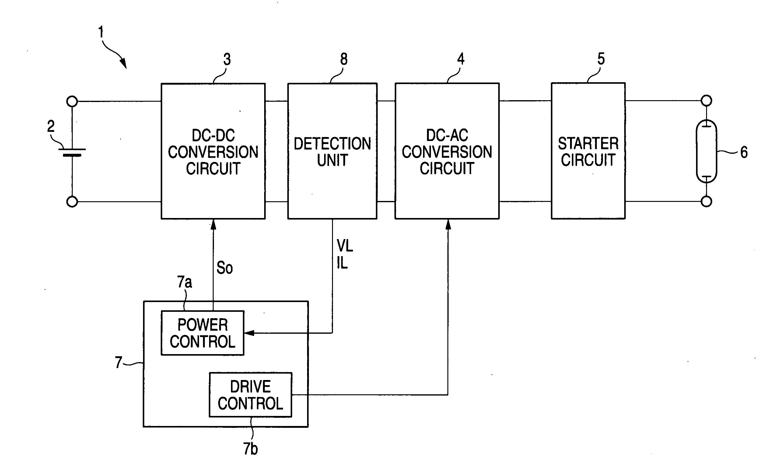
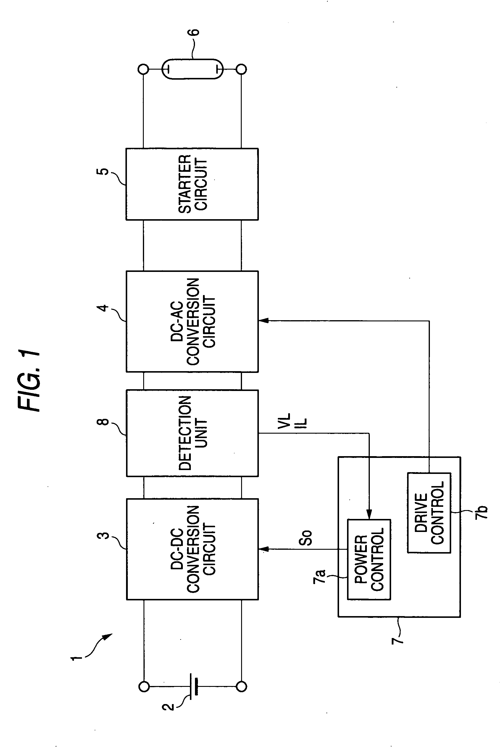
[0045]FIG. 1 is a diagram showing an exemplary, non-limiting configuration of the discharge lamp lighting apparatus 1. The discharge lamp lighting apparatus includes a DC power supply 2, a DC-DC conversion circuit 3, a DC-AC conversion circuit 4, a starting circuit (a so-called starter) 5, a discharge lamp 6 and a control circuit 7.

[0046] The DC-DC conversion circuit 3 acts to receive a DC input voltage from the DC power supply 2 and convert the input voltage into a desired DC voltage. For example, but not by way of limitation, a flyback-type DC-DC converter is used as the DC-DC conversion circuit.

[0047] The DC-AC conversion circuit 4 is provided to convert the output voltage of the DC-DC conversion circuit 3 into an AC voltage and supply the AC voltage to the discharge lamp 6. For example, but not by way of limitation, when the DC-AC conversion circuit is configured by an H-bridge type (or full-bridge type) circuit, two arms are formed by four semiconductor switching elements, dr...


PUM


Abstract

In the transient electric power control of a discharge lamp containing no mercury or a small amount of mercury, a change value relating to a lamp voltage from the initial value thereof is detected. A control unit is provided to change the temporal change rate of electric power supplied to the discharge lamp during the transient time period in accordance with the increase of the change value or the time lapse.

Description

[0001] The present invention claims foreign priority, based on Japanese patent application no. JP2004-209751, filed on Jul. 16, 2004, the contents of which is incorporated herein by reference in its entirety. This priority claim is being made concurrently with the filing of this application. BACKGROUND [0002] 1. Technical Field ,[0003] The present invention relates to a technique of realizing suppression of the variation of optical output and suppression of radiation noise in the transient power control of a discharge lamp that contains a small amount of mercury or no mercury. [0004] 2. Related Art [0005] In the case of using a discharge lamp for a lamp of an automobile, the light intensity must be quickly increased after starting the lighting of the discharge lamp. Accordingly, transient power control is performed such that, immediately after the lighting, an electric power larger than the steady lighting state power is supplied to the discharge lamp. Then, the electric power appli...

Claims


Application Information

Patent Timeline
IPC IPC(8): H05B37/02H05B41/288H05B41/38
CPCH05B41/386H05B41/2882H05B41/288H05B41/26
Inventor ICHIKAWA, TOMOYUKISERITA, TAKUYA
Owner KOITO MFG CO LTD
Learn More