
Circuit for driving an electronic component and method of operating an electronic device having the circuit

a technology of electronic components and circuits, applied in static indicating devices, instruments, electrical equipment, etc., can solve the problems of power transistors within driver circuits of oled technologies that can be on substantially longer times, and may be susceptible to threshold voltage changes

Active Publication Date: 2006-01-19
LG CHEM LTD
View PDF15 Cites 216 Cited by
  • Summary
  • Abstract
  • Description
  • Claims
  • Application Information

AI Technical Summary

Benefits of technology

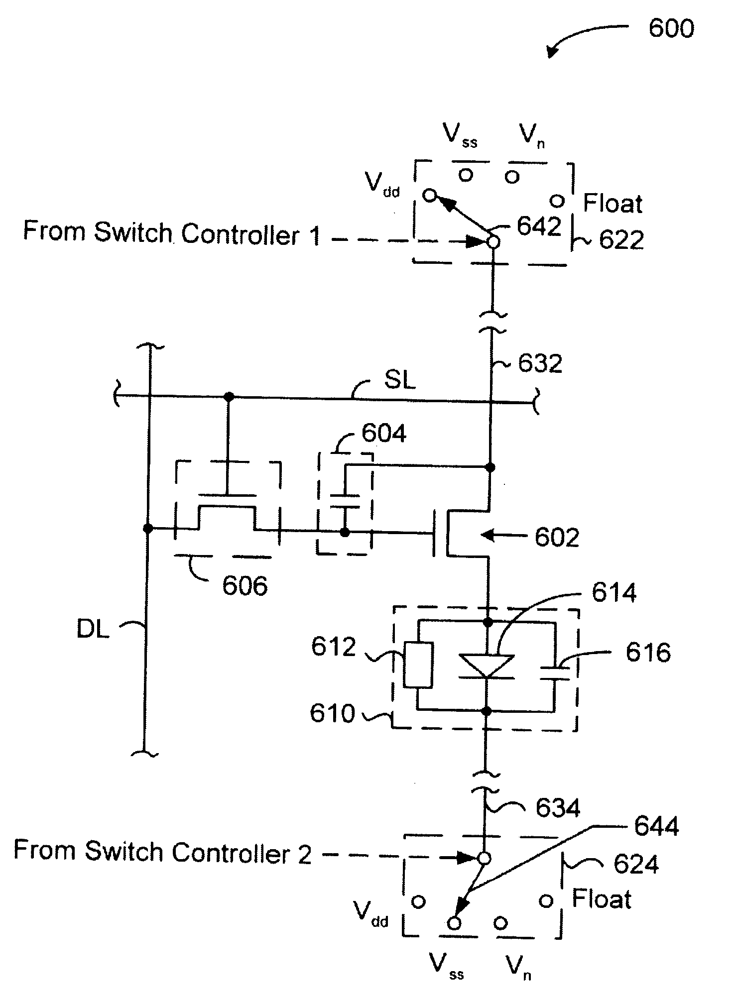
[0011] In still another embodiment, a method is used for operating an electronic device. The electronic device includes a field-effect transistor including a first source/drain region and a second source/drain region. The first source/drain region is connected to a first terminal of an electronic component. The electronic component is a radiation-emitting electronic component or a radiation-responsive electronic component. The method includes, during a first time period, sending a first signal to one of a second terminal of the electronic component or the second source/drain region. The method also includes, during a second time period, electrically floating the second terminal of the electronic component, the second source/drain region, or both.
[0012] In a further embodiment, a method is used for operating an electronic device. The elec

Problems solved by technology

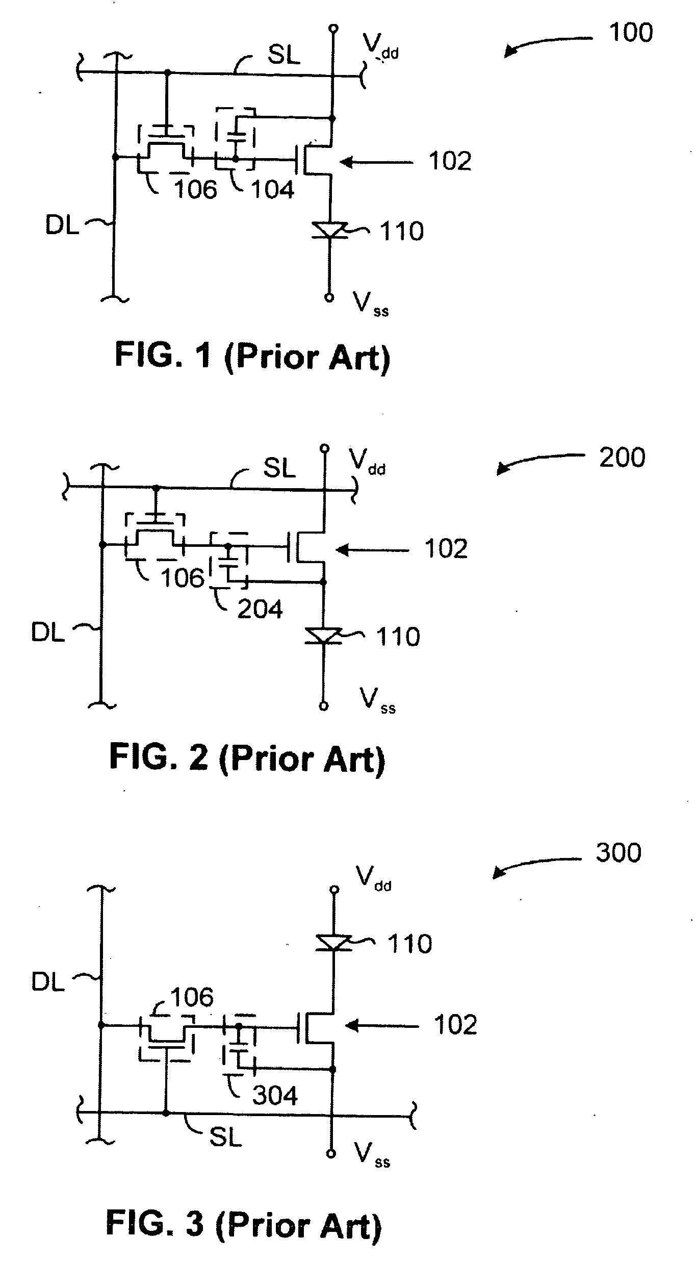
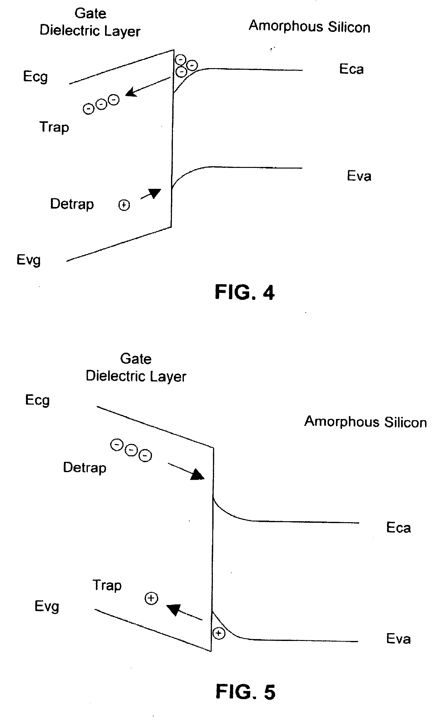
Metal-insulator-semiconductor field-effect transistors (“MISFETs”) may be susceptible to changes in threshold voltage due to charges that become trapped within a gate dielectric layer.
However, power transistors within driver circuits for OLED technologies can be on for substantially longer times.

Method used


Image

  • Circuit for driving an electronic component and method of operating an electronic device having the circuit
  • Circuit for driving an electronic component and method of operating an electronic device having the circuit
  • Circuit for driving an electronic component and method of operating an electronic device having the circuit

Examples


Embodiment Construction

[0024] In one embodiment, a circuit for driving an electronic component includes a first signal line and a first switch. The electronic component is a radiation-emitting electronic component or a radiation-responsive electronic component. The first switch is connected to the first signal line and is coupled to a first terminal of the electronic component. The first switch is configured to allow a state where the first signal line electrically floats.

[0025] In another embodiment, the circuit further includes a field-effect transistor including a gate electrode, a gate dielectric layer, a first source / drain region, and a second source / drain region. The gate electrode is coupled to a data line. The first source / drain region is connected to a first terminal of the electronic component.

[0026] In a specific embodiment, the circuit further includes a data holder unit having a first terminal and a second terminal. The first terminal of the data holder unit is connected to the gate electro...


PUM

PropertyMeasurementUnit
Timeaaaaaaaaaa
Lengthaaaaaaaaaa
Electric potential / voltageaaaaaaaaaa

Abstract

In one embodiment, a circuit for driving an electronic component includes a first signal line and a first switch. The first switch is connected to the first signal line and is coupled to a first terminal of the electronic component. The first switch is configured to allow a state where the first signal line electrically floats. In another embodiment, a circuit for driving an electronic component includes a first switch and a second switch. In yet another embodiment, a method for using any or all of the circuits includes electrically floating a second terminal of the electronic component, a source / drain region of a field-effect transistor, or both. In yet a further embodiment, during a first time period having a first switch at a first setting and a second switch at a second setting. During a second time period, changing the first switch, the second switch, or both to different setting(s).

Description

BACKGROUND OF THE INVENTION [0001] 1. Field of the Invention [0002] This invention relates in general to circuits and methods of operating electronic devices, and more particularly, to circuits for driving an electronic component and methods of operating electronic devices including the circuits. [0003] 2. Description of the Related Art [0004] Organic electronic devices have attracted considerable attention since the early 1990's. Examples of organic electronic devices include Organic Light-Emitting Diodes (“OLEDs”), which include Polymer Light-Emitting Diodes (“PLEDs”) and Small Molecule Organic Light-Emitting Diodes (“SMOLEDs”). Display devices, including OLED displays, have played an important role in modern human life. As computing, telecommunications, home entertainment, and networking technologies converge, the display unit will become more important. [0005] In the display area, there are many kinds of technologies including cathode ray tube (“CRT”), liquid crystal display (“L...

Claims


Application Information

Patent Timeline
IPC IPC(8): G09G3/30
CPCG09G3/3233G09G2300/0842Y10T29/49105G09G2310/0256G09G2320/043G09G2310/0254
Inventor CHEN, ZHININGSTEVENSON, MATTHEWYU, GANGZHANG, WEIXIAO
Owner LG CHEM LTD
Learn More