
Media dispenser and method for rejecting media

a dispenser and media technology, applied in the field of media dispensers, can solve the problems of inconvenient hand pick-up by customers, inconvenient disassembly of the media dispenser, and the prior art has some problems, so as to prevent theft and facilitate the design of the structure

Active Publication Date: 2006-01-19
ATEC AP CO LTD
View PDF12 Cites 20 Cited by
  • Summary
  • Abstract
  • Description
  • Claims
  • Application Information

AI Technical Summary

Benefits of technology

[0014] Another object of the present invention is to prevent a reject box in which rejected media are stored from separating from the media dispenser while an inlet of reject box is opened.
[0025] According to the present invention so constructed, since the media which the customer did not take out can be rejected at a time, there are advantages in that it is more convenient to reject the media and easy to design the structure for rejecting the media. In addition, the media are prevented from being stolen since the reject box is not separated from the media dispenser while an inlet of the reject box is opened.

Problems solved by technology

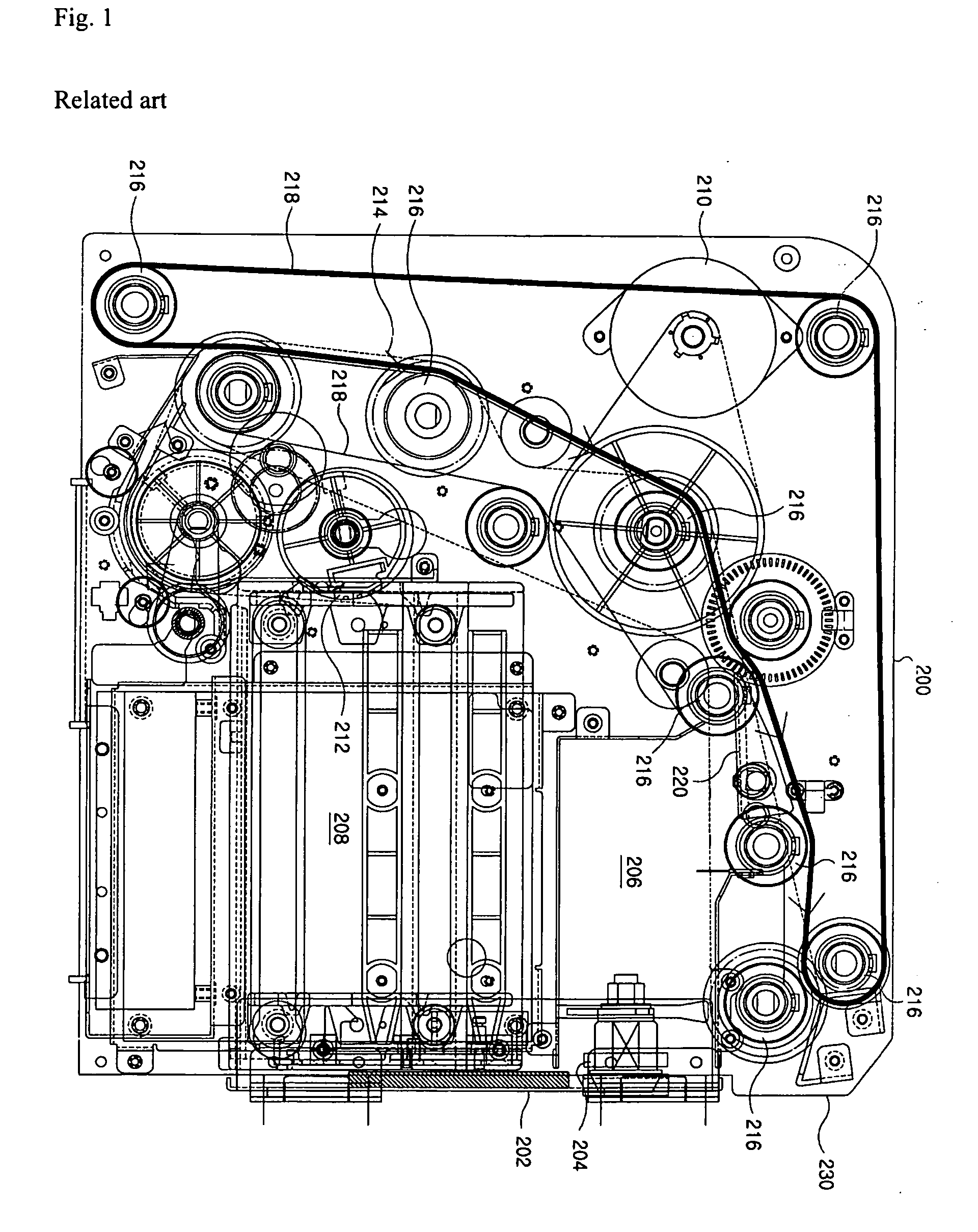
However, such a prior art has some problems as follows.
Thus, a number of the media are not closely stacked and become relatively large in volume, so that it is very inconvenient that the customer picks up them by hand.
Thus, that is also a problem since there is no way to feeding the media, which are once provided to the customer, into the media dispenser again at a time.
Further, since a variety of the components of the media dispenser are provided in the guide plates 200, there is inconvenience in that the media dispenser should be wholly disassembled in order to repair the components therein.
Furthermore, in the prior art, since the media may be taken out of the media dispenser in a state when an inlet of the reject box is opened, there is a problem in that the media rejected and stored in the reject box may be stolen.

Method used


Image

  • Media dispenser and method for rejecting media
  • Media dispenser and method for rejecting media
  • Media dispenser and method for rejecting media

Examples


Embodiment Construction

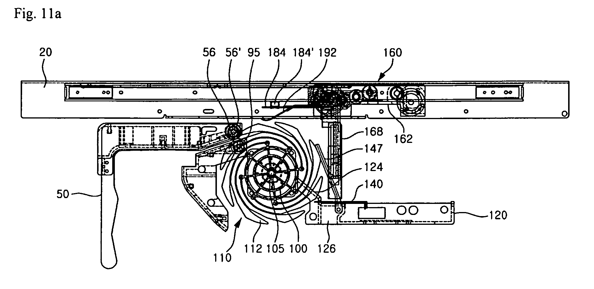
[0040] Hereinafter, a preferred embodiment of a media dispenser according to the present invention will be described in detail with reference to the accompanying drawings.

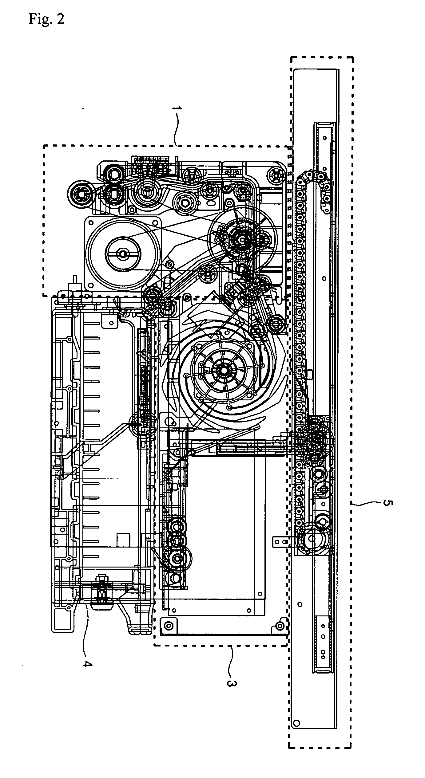
[0041] First, FIG. 2 is a side view generally showing the embodiment according to the present invention. FIG. 3 is a schematic perspective view showing the embodiment according to the present invention.

[0042] Referring to the figures, a media dispenser of the embodiment according to the present invention comprises a delivery module 1, a stacking module 3, and a delivery clamp module 5. The delivery module 1 serves to separate numbers of media from a media box (not shown), in which the media are stored, one by one and feed the media fed through a feed module (not shown) to a predetermined position. While feeding the media, the delivery module 1 also serves to divide the media into ones to be rejected and the others to be discharged by sensing thickness of the media. Reference numeral 4 designates a reject box.

[00...


PUM


Abstract

The present invention relates to a media dispenser and a method for rejecting media. According to the present invention, there is provided a media dispenser and a method for rejecting media. The media dispenser comprises a delivery module for feeding media, which come out of a media box, one by one; a stacking module for stacking the media, which are fed through the delivery module, on a stacking plate as many as a customer wants; and a delivery clamp module for clamping the media stacked on the stacking module and delivering the clamped media to the customer, and for feeding the media, which the customer did not take out, to the stacking plate, wherein a path through which the media clamped by the delivery clamp module are fed to a reject box is opened by moving the stacking plate of the stacking module. The method for rejecting media which a customer did not take out of the media dispenser as claimed in any one of claims 1 to 7, comprising the steps of: returning the media onto the stacking plate by a clamp assembly; opening a reject slot by allowing a driving plate to be moved by a driving source and the stacking plate to be moved together with the driving plate; and dropping the media as the clamp assembly unclamps the media through the opened reject slot. In the present invention, there are advantages in that it is convenient to reject the media and easy to design the structure for rejecting the media, and in that the media are prevented from being stolen.

Description

BACKGROUND OF THE INVENTION [0001] 1. Field of Invention [0002] The present invention relates to a media dispenser, and more particularly, to a media dispenser wherein a customer's desired number of media are collected and delivered at a time and a method for rejecting media which the customer did not take out of the media dispenser. [0003] 2. Description of the Prior Art [0004]FIG. 1 shows the constitution of a prior art media dispenser. According to the figure, various components for feeding media are provided between two guide plates 200 spaced apart by a predetermined interval from each other. A front surface of the media dispenser corresponding to an end of the guide plates 200 is provided with a door 202 for selectively opening or closing a predetermined space formed between the guide plates 200. The door 202 is installed to the guide plates 200 to be opened or closed about a hinge. Reference numeral 204 designates a locking member for keeping the door 202 closed. [0005] In th...

Claims


Application Information

Patent Timeline
IPC IPC(8): B65H29/20
CPCB65H29/20B65H2701/1912B65H31/3045G07F19/00
Inventor KO, KYUNG-HO
Owner ATEC AP CO LTD
Learn More