Precision dispense pump

Active Publication Date: 2006-01-12
SAINT GOBAIN PERFORMANCE PLASTICS CORP
View PDF17 Cites 16 Cited by
  • Summary
  • Abstract
  • Description
  • Claims
  • Application Information

AI Technical Summary

Benefits of technology

[0013] Precision dispense valves constructed in this manner are capable of consistently dispensing extremely accurate quantities of fluids, such as those used in the semiconductor manufacturing industry, on a noncontiguous

Problems solved by technology

Typically, syringe pumps that may be used in this type of application are not acceptable for at least two reasons.
First, the seal in a syringe pump is known to be the source of a percentage of leakage.
Such leakage is not desired due both to the possibility of inaccurate fluid dispensement, and due to the possibility of safety issues due to the aggressive nature of the process fluids being dispensed should they be allowed to escape into the workplace environment.
Additionally, the seal in the syringe pump is a dynamic member that is known to become worn during use.
The wearing of such seal would be the source of unwanted particle generation that would introduce unwanted contaminate particles into the process fluid.
Peristaltic pumps that are typically used in such application are also known to have significant particle generation issues, as well as not being able to consistently provide a desired dispensement accuracy at the levels required by the industry.

Method used


Image

  • Precision dispense pump
  • Precision dispense pump
  • Precision dispense pump

Examples


first embodiment

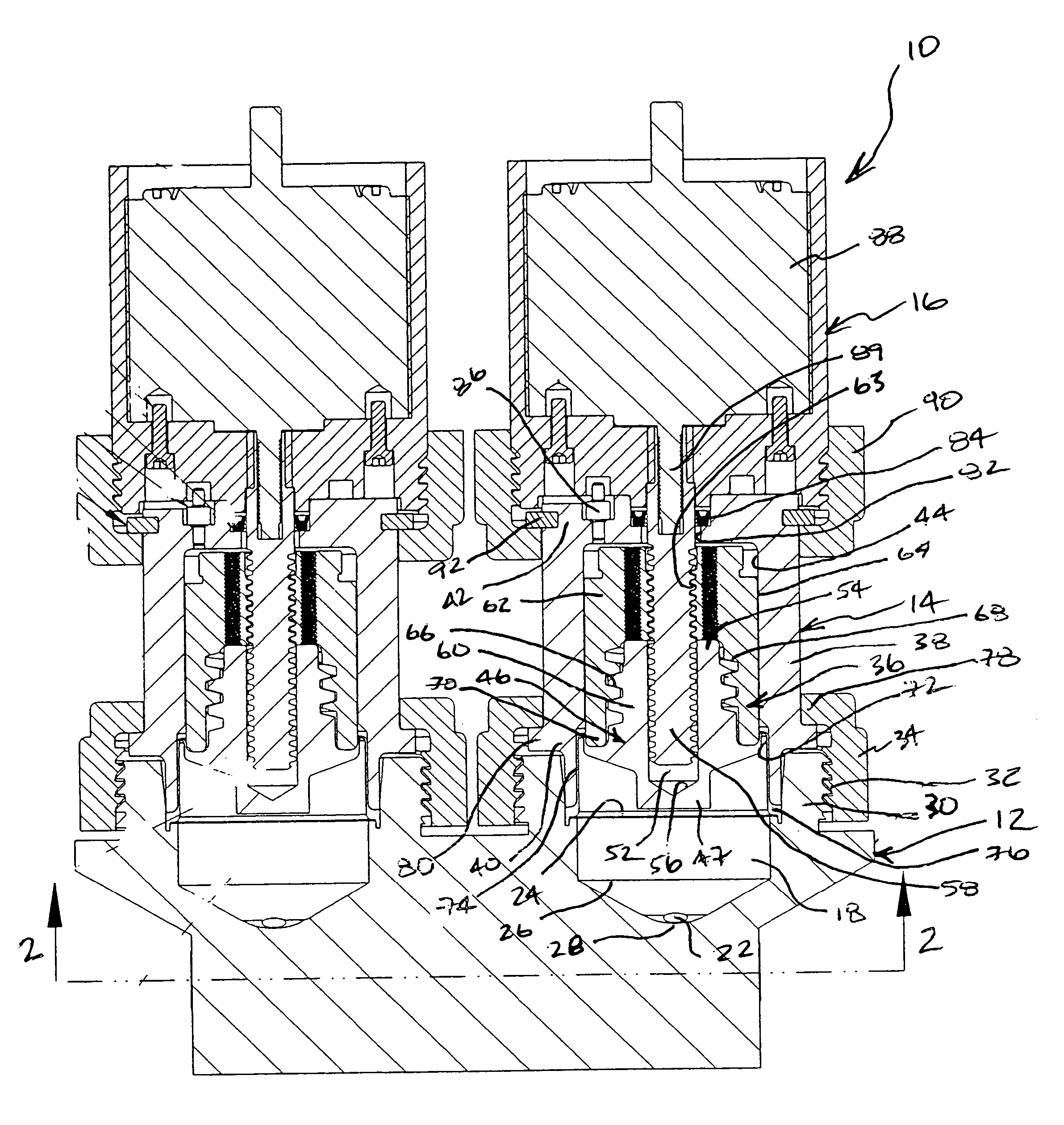
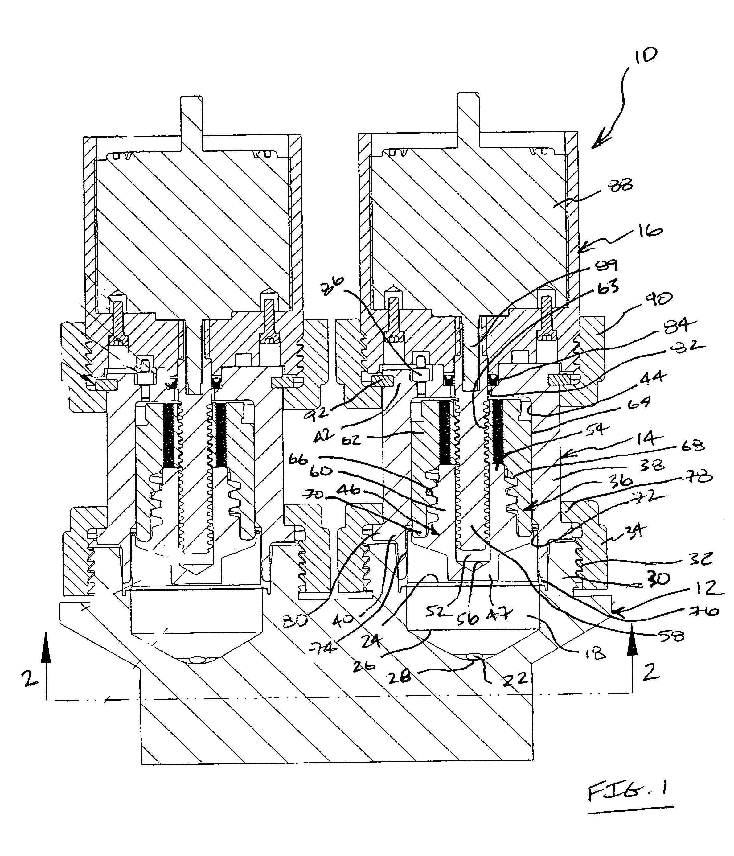
[0027]FIG. 1 illustrates a first embodiment precision dispense pump 10 of this invention in the form of a dual pump assembly, i.e., comprising two pressurizing chambers and respective pressurizing assemblies as better described below. While a dual pump assembly is illustrated, it is to be understood that precision dispense pumps of this invention can be configured in the form of a single pump assembly, i.e., having a single pressurizing chamber and respective pressurizing assembly, or in the form of a multi-pump assembly, i.e., comprising more than one pressurizing chamber and respective pressurizing assembly. The particular configuration of the pump will depend on the particular pump application. For example, for applications calling for the precision dispensement of fluid on a continuous basis, pumps of this invention will be configured having a multiple pump assembly, and for applications calling for the precision dispensement of fluid on a noncontinuous basis, a single pump asse...

third embodiment

[0066] The chamber body 202 is attached to a valve body 203 that includes a fluid inlet 210 and a fluid outlet 212 that are each in fluid flow communication with respective fluid inlet and fluid outlet ports that extend from the body fluid chamber (not shown). The internal specifics of the pressurizing assembly housing 204 and the valve body 203 will be described in greater detail below, with respect to a third embodiment dual pump assembly embodiment of this invention. The chamber body 202 can be attached to the valve body by conventional methods, such as by screwed attachment.

[0067] Unlike the flap-type check valves that were used in the first embodiment pump, the second embodiment pump uses poppet valve mechanisms that are disposed in the valve body for providing checked one-way flow of fluid through the pump. Referring to FIG. 6, in an example embodiment, the valve body 203 includes poppet valve mechanisms 216 and 218 for each of the fluid inlet and the fluid outlet, respectivel...

second embodiment

[0069] The second embodiment precision dispense pump, comprising a single pump assembly, is useful for those applications calling for a repeated or noncontinuous rather than a continuous dispensement of fluid. In an example embodiment, such single pump assembly can be configured to accurately repeatably dispense a volume of approximately 38.5 cubic centimeters per cycle and can be controlled to dispense up to about 250 cubic centimeters per minute.

[0070] FIGS. 7 to 10 illustrate a third embodiment precision dispense pump 300 constructed in accordance with this invention. Like the first pump embodiment disclosed above and illustrated in FIGS. 1 to 3, the third embodiment precision dispense pump also comprises a dual pump assembly, i.e., including two pressurizing chambers and respective pressurizing assemblies. However, the elements disposed within the pressurizing assembly housing comprising the pressurizing assembly are somewhat different than that disclosed for the first embodimen...


PUM


Abstract

Precision dispense pumps comprise a housing that has an internal chamber disposed therein. A pressurizing assembly disposed within the chamber and includes a cylindrical pressurizing member having a head, a thin-walled skirt extending axially away from the head, and a flange is positioned circumferentially around the skirt. The pressurizing assembly includes a support coupled to backside of the pressurizing member. The support has a cylindrical outside surface sized support the skirt when it is translated from a chamber surface during pressurizing assembly axial movement. A shaft projects through an opening in the support and into a partial opening in the pressurizing member. A fluid transport body is attached to the housing and includes a fluid chamber having a fluid inlet port and a fluid outlet port. An actuator is disposed within an actuator housing attached to the housing and is coupled to the shaft to cause axial movement of the pressurizing assembly within the housing chamber. The pump can includes a vacuum assist element connected to the housing to provide a desired pressure differential within the pump to bias the skirt against supportive chamber or support surfaces during pressurizing assembly movement. Check valves are in fluid flow communication with the fluid inlet and fluid outlet ports to ensuring checked one-way passage of fluid into and out of the fluid chamber during respective intake and output strokes of the pressurizing assembly.

Description

FIELD OF THE INVENTION [0001] The present invention relates generally to positive displacement pumps and, more particularly, to positive displacement pumps that are specially designed to repeatably or continuously dispense fluid in an extremely accurate manner. BACKGROUND OF THE INVENTION [0002] Positive displacement pumps are used in, for example, the semiconductor manufacturing industry for the purpose of dispensing high-purity process fluids such as corrosive and / or caustic process fluids for semiconductor processing. In such application, it is important that the volume of the process fluid being dispensed be accurate, that the accuracy of fluid dispensement be consistent. It is also important that the process fluid being dispensed be done in a manner that maintains its high level of purity. Accordingly, it is important that pumps placed into such service not introduce contaminant matter that can be transferred downstream, which could eventually damage or contaminate the high-pur...

Claims


Application Information

Patent Timeline
IPC IPC(8): F04B53/10F04B17/04F04B13/00F04B43/00
CPCF04B9/02F04B43/0054F04B13/00
Inventor KINGSFORD, KENJI A.BRIDGES, JOHN E. IIIMARTINEZ, DAVID R.
Owner SAINT GOBAIN PERFORMANCE PLASTICS CORP
Why Eureka
Try Eureka