
Downhole plug

a technology of downhole plugs and plugs, which is applied in the direction of wellbore/well accessories, fluid removal, earthwork drilling and mining, etc., can solve the problems of limited operation life of gaskets containing rubber or some other elastomer, weak structural strength, and inability to contra

Active Publication Date: 2006-01-12
INTERWELL NORWAY AS
View PDF3 Cites 34 Cited by
  • Summary
  • Abstract
  • Description
  • Claims
  • Application Information

AI Technical Summary

Benefits of technology

[0006] By use of the inventive downhole plug, it is possible to provide a secure seal during the most extreme conditions of utilization, regarding pressure and temperature. Furthermore, the new downhole plug can be removed from the well without failure, due to the design of the seal elements (“dogs”) and their fastening.

Problems solved by technology

), gaskets containing elements of rubber or some other elastomer will have a limited operating life.
This design, however, is structurally weak when removing the downhole plug after use.
A substantial disadvantage with this sealing sleeve is that it does not contract when the axial pressure effect is removed.
This proposal is thus not very suitable for downhole plugs, intended to temporarily seal wells, and to be removed after use.

Method used


Image

  • Downhole plug
  • Downhole plug
  • Downhole plug

Examples


Embodiment Construction

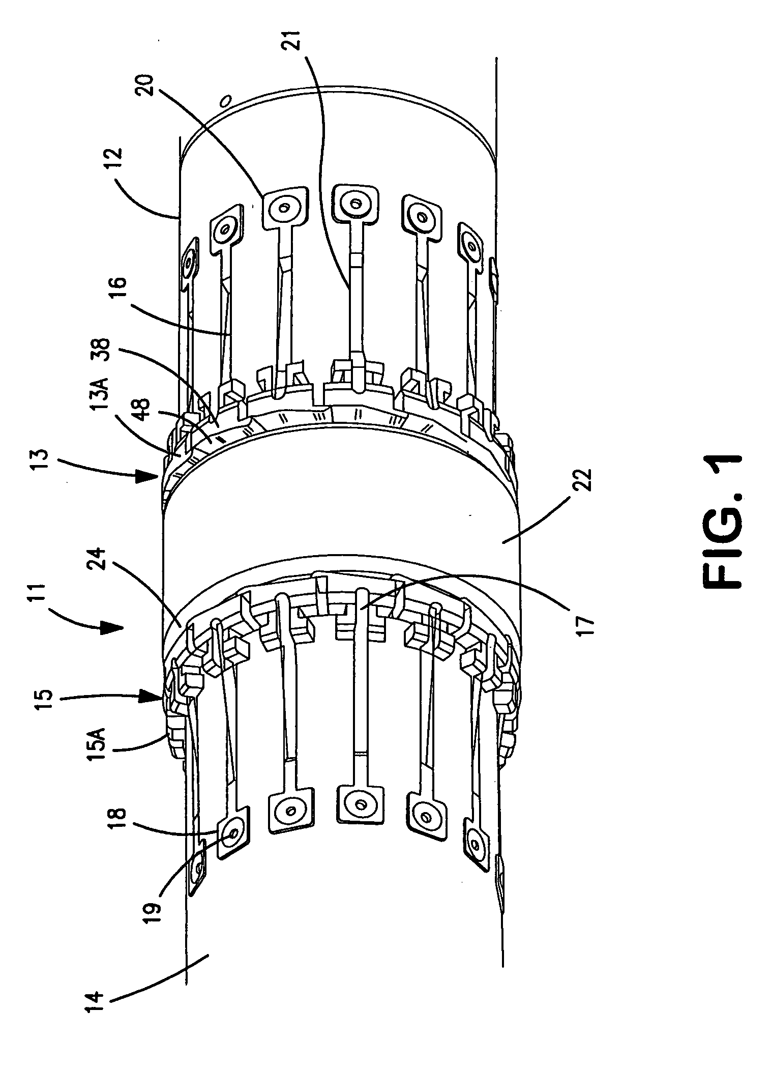
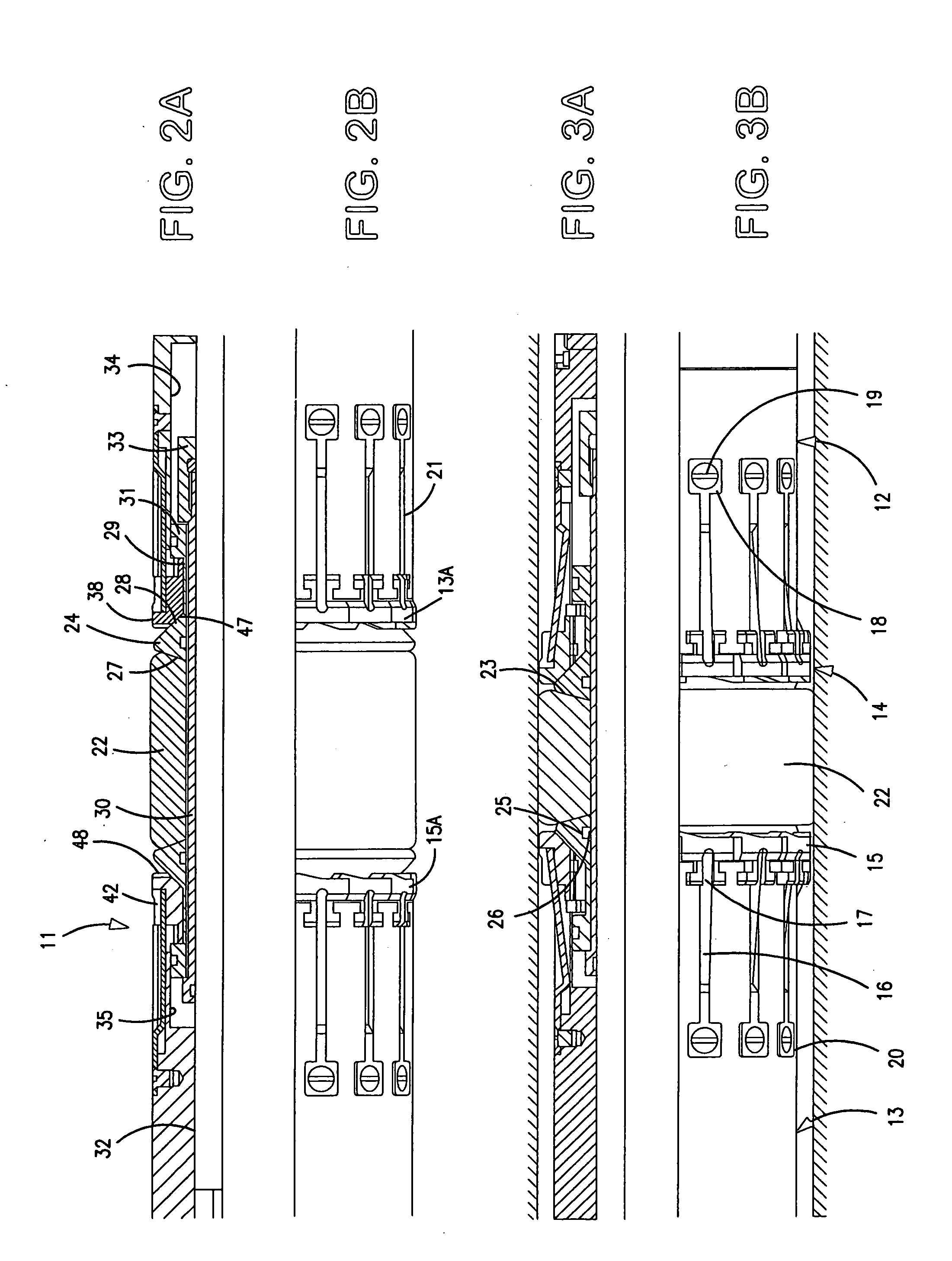
[0012] The downhole plug 11 in FIG. 1 is shown in a horizontal position, however, it will, in practice, be used in wells that are vertical, and wells that are at different angles relative to this direction. For the different elements the terms “upper” and “lower” are used, related to its normal orientation. The downhole plug has an upper annular casing 12, on the right side of the drawing, which accommodates an upper annular series 13 of seal elements 13A and a lower annular casing 14 for a corresponding annular series 15 of lower seal elements 15A.

[0013] Each annular series 13, 15 of seal elements 13A, 15A, contains, in the example, fourteen seal elements, but this number may vary, depending on the diameter of the downhole plug and the design of the seal elements 13A, 15A.

[0014] A leaf shaped compression spring 16 biases each of the seal elements 13A, 15A. The compression spring 16, is, at one end, fixed to the adjacent casing 12 or 14. At the seal elements 13A, 15A, the compress...


PUM


Abstract

Downhole plug, especially designed for closing an annular conduit in an oil or gas well, under high pressure and temperature. It has two radially expandable ring elements 13, 15, which are arranged on a carrying cylindrical element 32, between two mutually axially movable pressure elements 12, 14, having an expansion sleeve in between. The ring elements can, by insertion of the downhole plug in a well, be expanded from an inner position, seen radially, to a sealing position against the wall of the well. The radially expandable ring elements 13, 15, comprises a closed series of circumferentially overlapping seal elements 13A, 15 A. By the expanding movement they are mutually moved in the circumferential direction, thereby maintaining a seal against each other. They form an outer sealing surface 38, which can provide a seal against a cylindrical pipe wall, and they have an inwards facing sealing surface 47.

Description

BACKGROUND OF THE INVENTION [0001] The present invention relates to a downhole plug, especially for use in oil and gas wells, which contain high pressure and temperature. [0002] For the sealing of oil and gas wells which are to be either temporarily or permanently shut off, generally, a downhole plug is used which seals the well by means of expanding gaskets. In wells under high pressure (e.g. higher than say 5000 psi), combined with high temperature (e.g. higher than 150° C.), gaskets containing elements of rubber or some other elastomer will have a limited operating life. Thus, downhole plugs having metal gaskets which can stand exposure to substantially higher pressures and temperatures than pure elastomer gaskets have been proposed. [0003] EP patent specification 1277915 (Shell Int. Research, 2003) discloses the making of downhole plugs where the gasket element comprises a series of metal sleeves, positioned after each other along a core, and having an edge overlap. To seal, the...

Claims


Application Information

Patent Timeline
IPC IPC(8): E21B23/06E21B33/128E21BE21B33/12
CPCE21B33/128E21B33/1208
Inventor HIORTH, ESPENNERVIK, ASBJORN
Owner INTERWELL NORWAY AS
Learn More