
Remote data mirroring

a remote data and mirroring technology, applied in the field of data storage, can solve the problems of inability to back up data, low cost, and inability to provide primary as well as secondary or backed up data to the user, and achieve the effect of less manpower and facilities and cost reduction

Inactive Publication Date: 2006-01-05
EMC CORP
View PDF5 Cites 229 Cited by
  • Summary
  • Abstract
  • Description
  • Claims
  • Application Information

AI Technical Summary

Benefits of technology

[0023] In one embodiment, cache loading and processing speed is enhanced by queuing pointers to data in cache for transmission to the link, and permitting pending write data to be overwritten in cache. Link traffic can also be reduced in this case, since obsolete write pending data need not be transmitted over the link. However, unless the remote mirroring is operated in the synchronous mode, data integrity is subject to the possibility of a “rolling disaster.” In the rolling disaster, a remote mirroring relationship exists between the two data storage systems. All links break between the sites, and application processing continues using the primary (R1) volumes. The links are restored, and resynchronization commences by copying data from the primary (R1) volumes to the secondary (R2) volumes. Before resynchronization is finished, however, the primary volumes are destroyed, and the attempt at resynchronization has further corrupted the secondary volumes, due to the cache overwrite option.
[0033] Such a system is provided which is generally lower in cost and requires substantially less manpower and facilities to achieve than the prior art devices.

Problems solved by technology

Should a disaster such as fire, flood, or inaccessibility to a building occur, however, both the primary as well as the secondary or backed up data will be unavailable to the user.
This process is very time consuming and cost intensive, both in maintaining an accurate catalog of the data stored on each individual tape, as well as storing the large number of tapes required to store the large amounts of data required by these institutions.
Additionally and most importantly, it often takes twenty-four hours before a back-up tape reaches its storage destination during which time the back-up data is unavailable to the user.
Additionally, today's systems require a significant amount of planning and testing in order to design a data recovery procedure and assign data recovery responsibilities.
Such testing may take days or even weeks and always involves significant human resources in a disaster recovery center or back-up site.
Such a proposed method, however, overly burdens the host CPU with the task of writing the data to a secondary storage system and thus dramatically impacts and reduces system performance.

Method used


Image

  • Remote data mirroring
  • Remote data mirroring
  • Remote data mirroring

Examples


Embodiment Construction

[0059] A. Overview

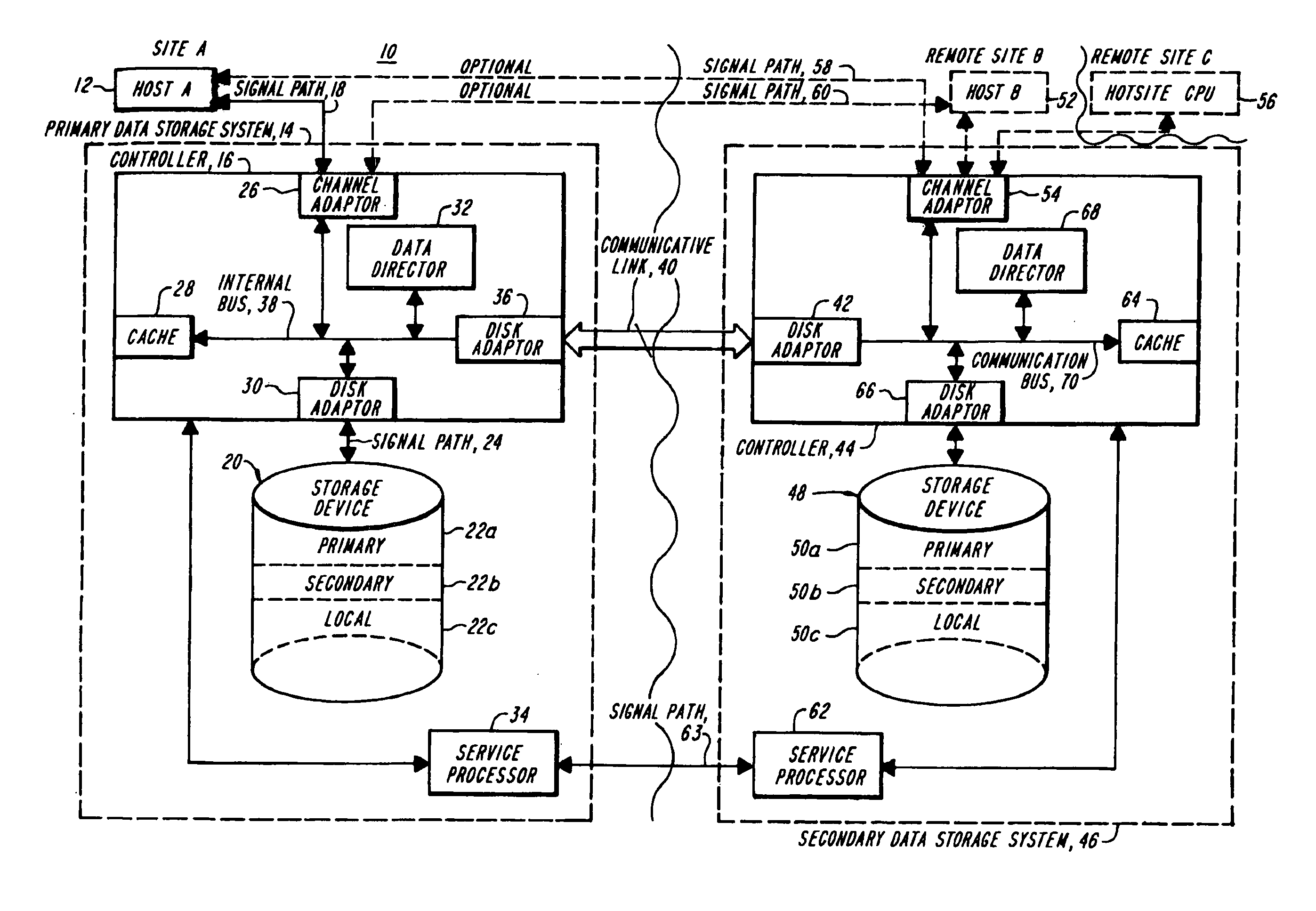
[0060] The present invention features a system which provides a geographically remote mirrored data storage system which contains generally identical information to that stored on a primary data storage system. Utilizing such a system, data recovery after a disaster can be nearly instantaneous and may require little, if any, human intervention. Using the present system, the data is retrieved from a remote device through the host data processing system.

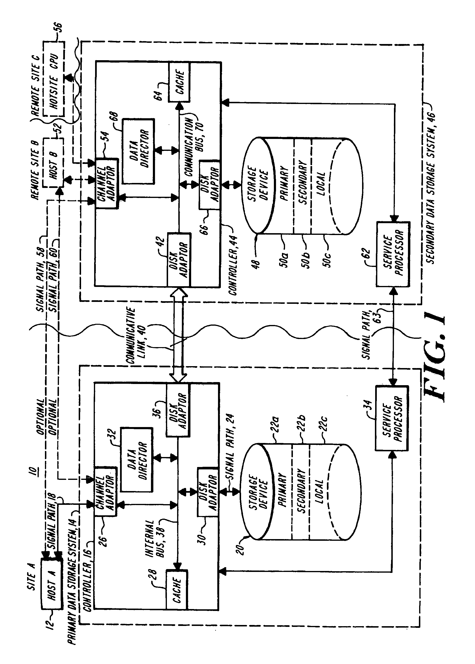
[0061] A system in accordance with the present invention is shown generally at 10, FIG. 1, and includes at site A, which is a first geographic location, a host computer system 12 as is well known to those skilled in the art. The host computer system 12 is coupled to a first and primary data storage system 14. The host 12 writes data to and reads data from the primary data storage system 14.

[0062] The primary data storage system 14 includes a primary data storage system controller 16 which receives data from the hos...


PUM

PropertyMeasurementUnit
distancesaaaaaaaaaa
link distanceaaaaaaaaaa
volumesaaaaaaaaaa

Abstract

Two data storage systems are interconnected by a data link for remote mirroring of data. Each volume of data is configured as local, primary in a remotely mirrored volume pair, or secondary in a remotely mirrored volume pair. Normally, a host computer directly accesses either a local or a primary volume, and data written to a primary volume is automatically sent over the link to a corresponding secondary volume. Each remotely mirrored volume pair can operate in a selected synchronization mode including synchronous, semi-synchronous, adaptive copy-remote write pending, and adaptive copy-disk. Direct write access to a secondary volume is denied if a “sync required” attribute is set for the volume and the volume is not synchronized.

Description

RELATED APPLICATIONS [0001] This application is a continuation of U.S. patent application Ser. No. 10 / 330,715 filed Dec. 27, 2002, which is a continuation of U.S. patent application Ser. No. 09 / 709,814 filed Nov. 10, 2000 (U.S. Pat. No. 6,502,205 issued Dec. 31, 2002), which is a divisional of U.S. patent application Ser. No. 09 / 061,708 filed Apr. 17, 1998 (U.S. Pat. No. 6,173,377 issued Jan. 9, 2001), which is a continuation of U.S. patent application Ser. No. 08 / 654,511 filed May 28, 1996 (U.S. Pat. No. 5,742,792 issued Apr. 21, 1998), which is a continuation-in-part of U.S. patent application Ser. No. 08 / 052,039 filed Apr. 23, 1993, entitled REMOTE DATA MIRRORING (U.S. Pat. No. 5,544,347 issued Aug. 6, 1996), which are all incorporated herein by reference. [0002] Authorization Pursuant to 37 C.F.R § 1.17(e) [0003] A portion of the disclosure of this patent document contains command formats and other computer language listings all of which are subject to copyright protection. The ...

Claims


Application Information

Patent Timeline
Patent Type & Authority Applications(United States)
IPC IPC(8): G06F11/00G06F3/06G06F12/16G06F11/14G06F11/20G06F12/00G06F13/00G11B20/12H04L29/06
CPCG06F3/0601Y10S707/99942G06F3/061G06F3/0619G06F3/064G06F3/065G06F3/0661G06F3/0689G06F11/2066G06F11/2071G06F11/2074G06F11/2079G06F11/2082G06F2003/0697G11B20/1217H04L29/06H04L67/1095H04L69/26H04L69/40G06F3/0608H04L9/40
Inventor YANAI, MOSHEVISHLITZKY, NATANALTERESCU, BRUNOCASTEL, DANIEL D.C.SHKLARSKY, GADI G.OFEK, YUVAL Y.O.
Owner EMC CORP
Learn More