
Thread-based clock enabling in a multi-threaded processor

Active Publication Date: 2006-01-05
ORACLE INT CORP
View PDF54 Cites 47 Cited by
  • Summary
  • Abstract
  • Description
  • Claims
  • Application Information

AI Technical Summary

Benefits of technology

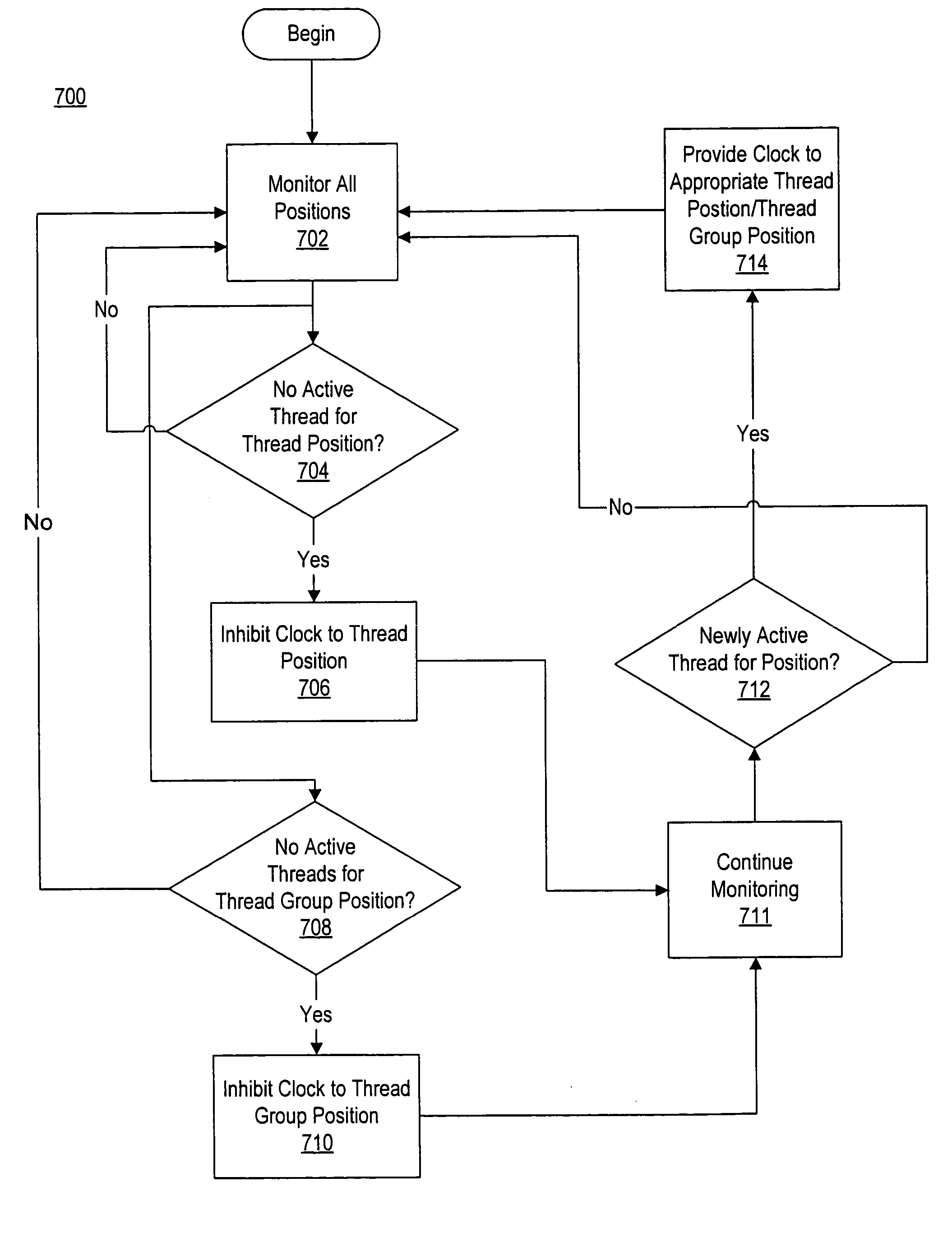
[0006] A method and apparatus for controlling power consumption in a multi-threaded processor is disclosed. In one embodiment, the processor includes at least one logic unit for processing instructions. The logic unit includes a plurality of positions, wherein each of the plurality of positions corresponds to at least one instruction thread. Clock signals may be provided to the logic unit via a clock gating unit. The clock gating unit is configured to inhibit a clock signal from being provided to a corresponding one of the thread positions when no instruction thread is active for that position. The inhibiting of the clock signal for an inactive thread position may reduce power consumption by the processor.

Problems solved by technology

Modern computer system processors consume a significant amount of power.
Thus, such a processor may easily consume in excess of 100 watts of power even at system voltages as low as one volt.
High power consumption can generate large amounts of heat which, if left unchecked, can adversely affect the operation of the processor and the computer system in which it is implemented.
Thus, high power consumption and the potential for excess heat generation place significant engineering demands on the design of computer systems.
However, the core of a processor typically cannot be powered down during system activity.
The current consumed by the core of a processor may account for a large amount of its overall current consumption.
Furthermore, activity in the core typically affects other units within the processor, and often times the entire computer system, and thus serves as a major driver of overall power consumption.

Method used


Image

  • Thread-based clock enabling in a multi-threaded processor
  • Thread-based clock enabling in a multi-threaded processor
  • Thread-based clock enabling in a multi-threaded processor

Examples


Embodiment Construction

Overview of Multithreaded Processor Architecture

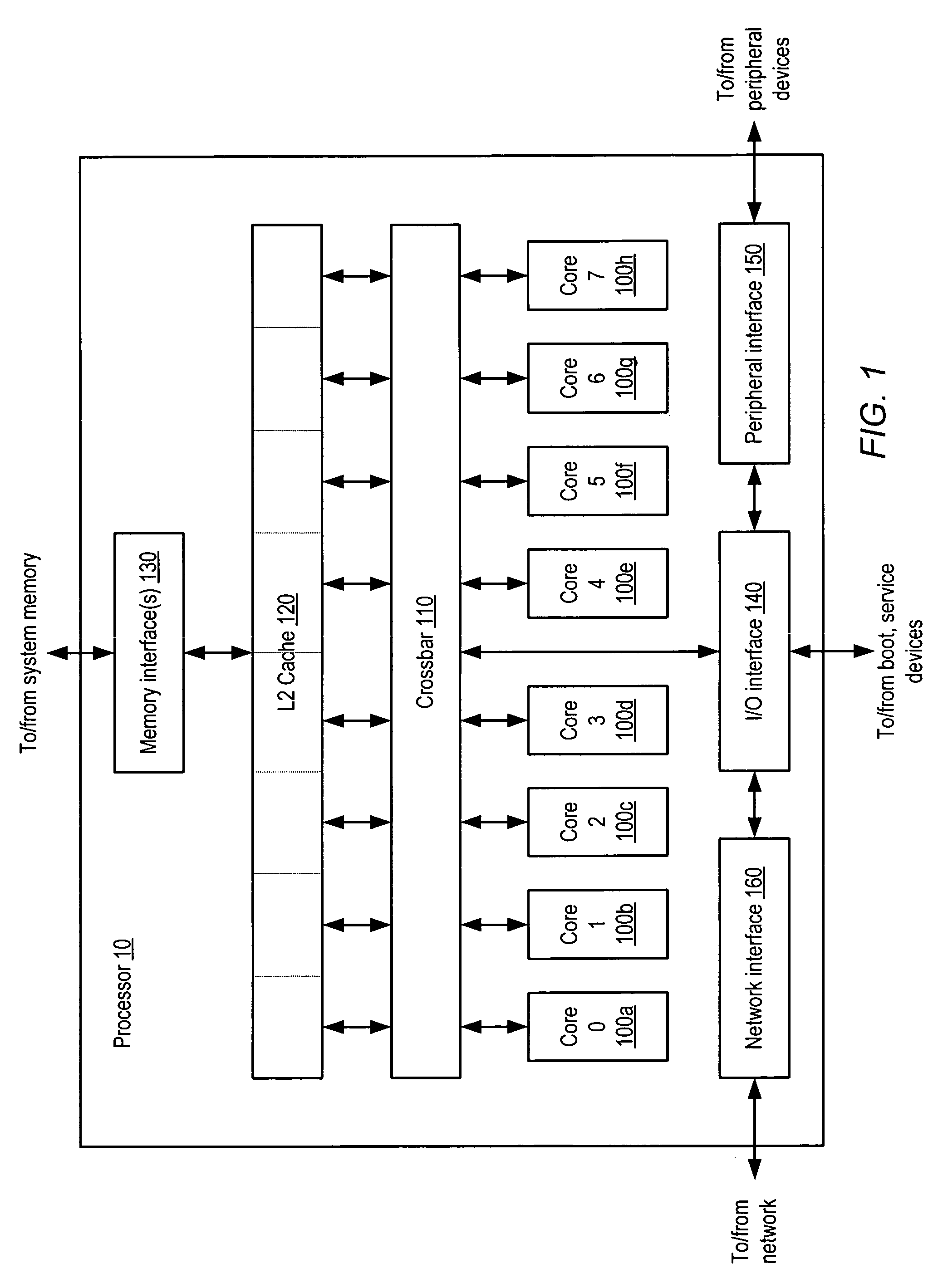
[0019] A block diagram illustrating one embodiment of a multithreaded processor 10 is shown in FIG. 1. In the illustrated embodiment, processor 10 includes a plurality of processor cores 100a-h, which are also designated “core 0” though “core 7”. Each of cores 100 is coupled to an L2 cache 120 via a crossbar 110. L2 cache 120 is coupled to one or more memory interface(s) 130, which are coupled in turn to one or more banks of system memory (not shown). Additionally, crossbar 110 couples cores 100 to input / output (I / O) interface 140, which is in turn coupled to a peripheral interface 150 and a network interface 160. As described in greater detail below, I / O interface 140, peripheral interface 150 and network interface 160 may respectively couple processor 10 to boot and / or service devices, peripheral devices, and a network.

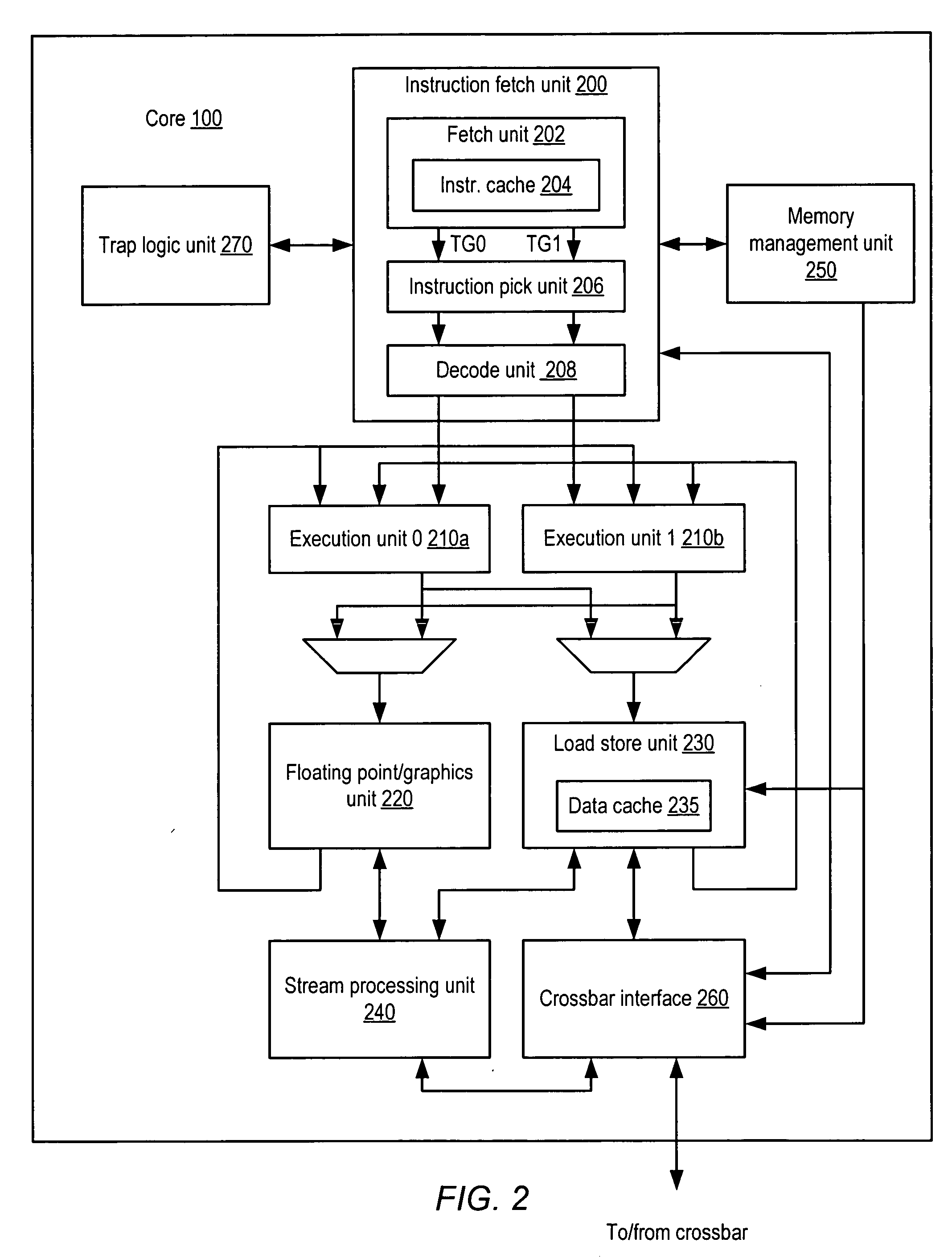
[0020] Cores 100 may be configured to execute instructions and to process data according to a particular instruct...


PUM


Abstract

A method and apparatus for controlling power consumption in a multi-threaded processor. In one embodiment, the processor includes at least one logic unit for processing instructions. The logic unit includes a plurality of positions, wherein each of the plurality of positions corresponds to at least one instruction thread. Clock signals may be provided to the logic unit via a clock gating unit. The clock gating unit is configured to inhibit a clock signal from being provided to a corresponding one of the thread positions when no instruction thread is active for that position. The inhibiting of the clock signal for an inactive thread position may reduce power consumption by the processor.

Description

BACKGROUND OF THE INVENTION [0001] 1. Field of the Invention [0002] This invention relates to computer systems, and more particularly, to power conservation in computer system processors. [0003] 2. Description of the Related Art [0004] Modern computer system processors consume a significant amount of power. It is not uncommon for the current consumption of a modern processor to exceed 100 amperes. Thus, such a processor may easily consume in excess of 100 watts of power even at system voltages as low as one volt. High power consumption can generate large amounts of heat which, if left unchecked, can adversely affect the operation of the processor and the computer system in which it is implemented. Thus, high power consumption and the potential for excess heat generation place significant engineering demands on the design of computer systems. [0005] Various methods of power conservation are employed in computer systems. In many computers, various system components that are inactive m...

Claims


Application Information

Patent Timeline
IPC IPC(8): G06F1/26
CPCY02B60/1221G06F9/3851G06F1/3237Y02B60/1278G06F1/3287G06F1/3203Y02B60/1282Y02D10/00G06F9/3888
Inventor GOLLA, ROBERT T.BROOKS, JEFFREY S.OLSON, CHRISTOPHER H.
Owner ORACLE INT CORP
Learn More