
Target detecting device and target capturer, device and method for molecular adsorption or desorption, and device and method for protein detection

a target detection and target technology, applied in the field of target detection devices and target capturers, and the use of specific bioreactors/fermenters, to achieve the effect of reducing the speed of molecular diffusion and achieving highly efficient analysis and/or diagnosis

Inactive Publication Date: 2006-01-05
FUJITSU LTD
View PDF14 Cites 21 Cited by
  • Summary
  • Abstract
  • Description
  • Claims
  • Application Information

AI Technical Summary

Benefits of technology

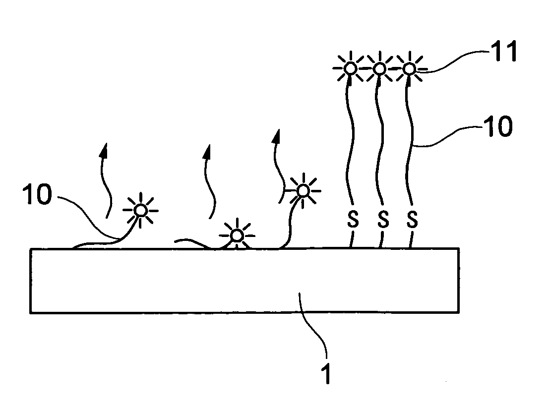
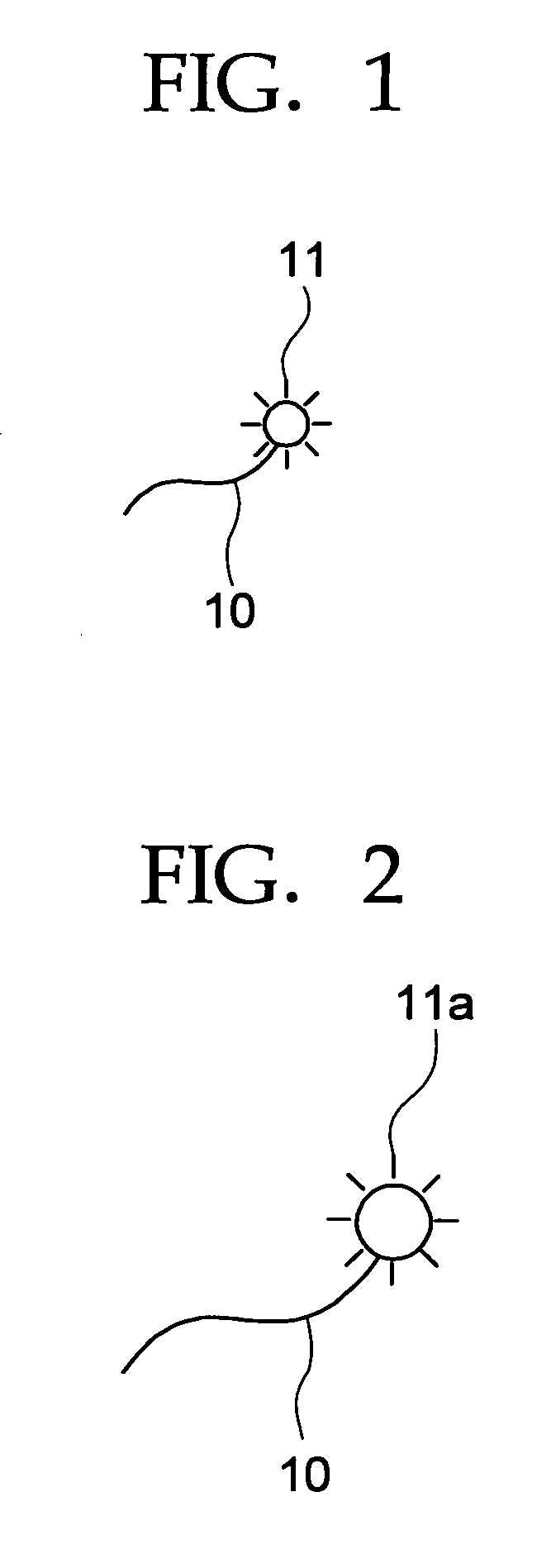
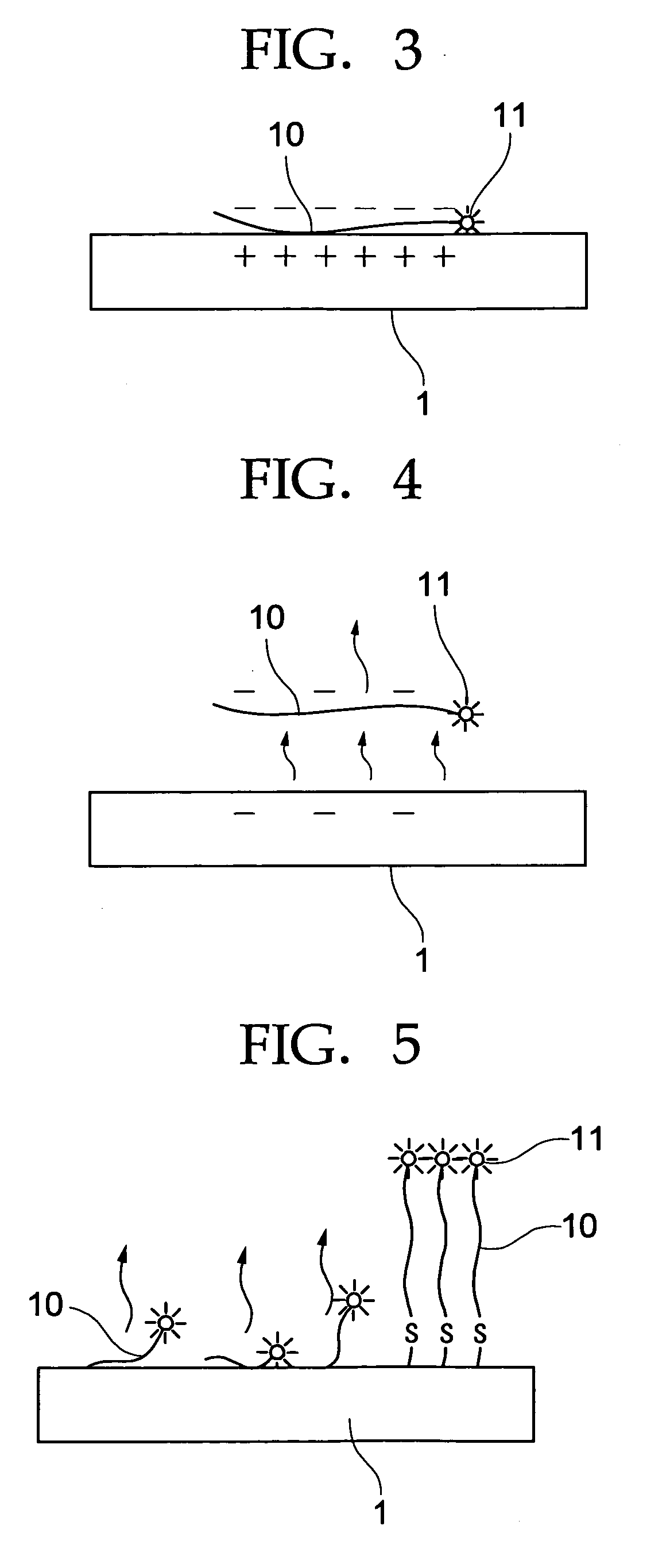
[0028] The present invention provides a target capturer comprising an interacting section, a capturing section and a light emitting section, the interacting section at least partially containing a region interactive with an electrically conductive member, the capturing section capable of capturing a target, and the light emitting section capable of emitting light upon irradiation with light when the region in the interacting section does not interact with the electrically conductive member. In the target capturer of the present invention, at least part of the interacting section is capable of interacting with the electrically conductive member (for example, capable of electrically capturing the electrically conductive member). The capturing section is capable of capturing the target. The light emitting section is capable of emitting light upon irradiation with light when the interacting section is not interacting with the electrically conductive member (for example, being electrically bound). The use of the target capturer of the present invention can arbitrarily control light emission and detect the presence or absence of the target by utilizing the phenomenon that the speed of molecular diffusion is decreased when the target is captured.
[0029] The device for molecular adsorption or desorption of the present invention comprises two or more working electrodes (adsorption and / or desorption electrod) that are controlled independently, and are capable of undergoing at least one of molecular adsorption and molecular desorption. The device for molecular adsorption or desorption applies varying electric potentials to the two or more working electrodes with independently arbitrary different timings to thereby allow the working electrodes to adsorb or desorb the molecule with different timings arbitrarily. By changing the applied electric potentials to the two or more working electrodes to inverse potentials, the molecular desorption and adsorption can be reversibly carried out. By allowing the two or more working electrodes to adsorb two or more different molecules and applying varying electric potentials to the two or more working electrodes with independently arbitrary different timings, the two or more different molecules can be desorbed with different timings arbitrarily. Likewise, by applying varying electric potentials to the two or more working electrodes in an electrically conductive liquid containing two or more different molecules with independently arbitrary different timings, the two or more working electrodes can adsorb the two or more different molecules. The present invention has been accomplished based on the following findings. Namely, electrical control of the movement or migration, such as adsorption or desorption, of useful substances or molecules, such as DNAs, can provide diagnosing / analyzing devices useful in research and development in the area of biotechnologies. If the adsorption or desorption of the two or more different useful substances or molecules can be carried out using two or more electrodes with different timings arbitrarily, highly efficient analysis and / or diagnosis can be achieved. In addition, if the electrodes can be so designed as to have smaller exposed surfaces, the resulting devices can for example be down-sized, formed into chips and / or integrated.

Problems solved by technology

Thus, the light detecting means does not detect such light emitted by the target capturer.

Method used


Image

  • Target detecting device and target capturer, device and method for molecular adsorption or desorption, and device and method for protein detection
  • Target detecting device and target capturer, device and method for molecular adsorption or desorption, and device and method for protein detection
  • Target detecting device and target capturer, device and method for molecular adsorption or desorption, and device and method for protein detection

Examples


example 1

[0344] Initially, a single-stranded polynucleotide having twelve bases and containing (CH2)3 SS (CH2 )3OH at the three prime-end and the fluorescent dye represented by Structural Formula 1 and biotin at the five prime-end was synthetically prepared as the target capturer. In the target capturer, the fluorescent dye serves as the light emitting section, the biotin serves as the target capturing section, and the polynucleotide serves as the interacting section.

[0345] The target capturer was allowed to react with a polished circular metal electrode 1 (a gold electrode in this example) having a diameter of 7 mm at room temperature for 24 hours. The metal electrode 1 and a reference electrode facing the metal electrode 1 were placed in an electrolytic solution, a direct-current electric field was applied to between the two electrodes to thereby apply a positive electric field to the metal electrode 1 (gold electrode). Then, the single-stranded nucleotide serving as the interacting secti...

example 2

[0350] An example of the device or method for molecular adsorption or desorption or of the present invention is as mentioned above. A concrete test on the adsorption and desorption of the molecule in the working electrode will be illustrated below.

[0351] A gold electrode serving as the working electrode was formed on a quartz glass substrate as the substrate by vapor deposition. A dielectric film of silicon nitride was formed on the surface of the substrate and the gold electrode to expose part of the substrate and the gold electrode therefrom (FIGS. 10A and 10B). The gold electrode was evaluated by cyclic voltammetry, an electrochemical measuring process, and the result is shown in FIG. 22. The graph shows that the gold electrode has a low current at voltages from −0.7 V to 0.7 V, indicating that there is no significant oxidation-reduction reaction on the surface thereof, indicating that the gold electrode can be used without problems such as breakage in the application of a volta...

example 3

[0354] The device shown in FIGS. 24 and 25 was used herein.

[0355] Single-stranded oligonucleotides having a thiol group with the interposition of a spacer at the three prime-end were synthetically prepared by using a naturally-occurring single-stranded oligonucleotide and an artificial single-stranded oligonucleotide and were allowed to react with a polished gold electrode at room temperature for 24 hours reaction. Thus, the naturally-occurring single-stranded oligonucleotide and the artificial single-stranded oligonucleotide were allowed to bind with the gold electrode arranged on sapphire (FIG. 24). A fluorescent dye group had been introduced into the single-stranded oligonucleotides. The thiol group and the fluorescent dye group may be introduced at the end of the single stranded or at the five prime-end of the strand.

[0356] The oligonucleotide strands were immobilized to the circular gold electrode having a diameter of 1 mm. No quencher was used in the present example.

[0357] ...


PUM

PropertyMeasurementUnit
Electrical conductivityaaaaaaaaaa
Electric potential / voltageaaaaaaaaaa
Fluorescenceaaaaaaaaaa

Abstract

The present invention provides, for example, a target detecting device comprising a target capturer, means for releasing the target capturer, light irradiating means and light detecting means, the target capturer at least partially containing a region interactive with an electrically conductive member, being capable of capturing a target, and being capable of emitting light upon irradiation with light in the case of not interacting with the electrically conductive member, the means for releasing the target capturer serving to release the target capturer from the electrically conductive member by ceasing the interaction between the target capturer and the electrically conductive member, the light irradiating means serving to apply light to the electrically conductive member, and the light detecting means serving to detect light emitted by the target capturer upon irradiation of light applied by the light irradiating means. It also provides a target capturer comprising an interacting section, a capturing section and a light emitting section, the interacting section at least partially containing a region interactive with an electrically conductive member, the capturing section capable of capturing a target, and the light emitting section capable of emitting light upon irradiation with light when the region in the interacting section does not interact with the electrically conductive member.

Description

CROSS-REFERENCE TO RELATED APPLICATIONS [0001] This is a continuation of Application PCT / JP2003 / 015099, filed on Nov. 26, 2003.BACKGROUND OF THE INVENTION [0002] 1. Field of the Invention [0003] The present invention relates to a target detecting device capable of efficiently detecting a variety of targets such as proteins without labeling typically with fluorescence and to a target capturer that can be suitably used therein. [0004] The present invention relates to a device and method for molecular adsorption or desorption which are capable of efficiently and reliably adsorbing and / or desorbing one or more useful molecules such as DNAs with different timings arbitrarily, are capable of, for example, being down-sized, formed into chips and / or integrated and show high performance. [0005] The present invention also relates to a device and method for protein detection which are capable of detecting and quantitatively determining one or more protein without labeling. [0006] 2. Descriptio...

Claims


Application Information

Patent Timeline
IPC IPC(8): C12M3/00
CPCC12Q1/6816C12Q1/6825C12Q2565/607C12Q2565/107C12Q2523/308
Inventor FUJIHARA, TSUYOSHIFUJITA, SHOZOTAKEISHI, SHUNSAKUARINAGA, KENJIYAMAGUCHI, YOSHITAKAUSUKI, TATSUYA
Owner FUJITSU LTD
Learn More