
Plasma display device and driving method for use in plasma display device

a technology of plasma display device and display device, which is applied in the direction of static indicating device, address electrode, instrument, etc., can solve the problems of large power consumption of pdp, failure to produce satisfactory image, and uneven halftone display, so as to achieve satisfactory image, sufficient light emission luminance, and sufficient gradation levels

Inactive Publication Date: 2006-01-05
PIONEER CORP
View PDF6 Cites 5 Cited by
  • Summary
  • Abstract
  • Description
  • Claims
  • Application Information

AI Technical Summary

Benefits of technology

[0031] The present invention has been proposed to solve the foregoing problems, and it is an object of the invention to provide a plasma display device and a method of driving the same which are capable of ensuring sufficient levels of gradation for displaying a dark image while avoiding an increase in manufacturing cost, and sufficiently reducing the display luminance for the black level to display a satisfactory image.
[0043] According to an eleventh aspect of the present invention in the driving method according to the tenth aspect of the present invention, each of the unit cells is composed of two sub-cells, two of the discharge gaps between each scanning electrode of each surface discharge electrode pair and two of the discharge sustain electrodes placed on both sides of the scanning electrode cause two of the sub-cells to emit light, respectively, and a sub-cell driven to emit light is changed from one to another of the sub-fields to set a light emission luminance produced by one discharge sustain pulse in one or more of the sub-cells to be lower than the light emission luminance of the other sub-cells.
[0047] According to the configuration of the present invention, each unit cell is composed of a plurality of sub-cells, and a light emission luminance produced by one discharge sustain pulse in one or more of these sub-cells is set to be lower than a light emission luminance of the other sub-cells, so that a darker sub-cell can be made to have a sub-field of a lower level of gradation than the sub-field having the lowest level of gradation of a brighter sub-cell. Also, since the priming discharge in each sub-field is produced in the sub-cell which presents the lowest light emission luminance per discharge sustain pulse, the light emission luminance can be sufficiently reduced when black is displayed, thus making it possible to display a satisfactory image.
[0048] The present invention provides a plasma display device and a driving method for use in the plasma display device which can produce sufficient levels of gradation when a dark image is displayed by creating a darker sub-cell which has a sub-field of a lower level of gradation than the sub-field having the lowest level of gradation of a brighter sub-cell, and sufficiently reduce the display luminance for a black level by producing a priming discharge in the darker sub-cell.

Problems solved by technology

However, the discharge sustain pulse at a higher frequency causes larger power consumption of the PDP.
Therefore, as the luminance provided by each discharge sustain pulse is improved, a halftone display does not appear smooth in dark regions, failing to produce a satisfactory image.
This problem has come to the surface.
Since this priming discharge is also produced when black is displayed, an increase in luminance produced by the priming discharge causes a higher luminance of the black level, failing to produce a satisfactory image.
However, the conventional plasma display panels described above have the following problems.
This leads to a problem of a complicated configuration of a device and an inevitable increase in manufacturing cost.
Also, the problem of an increased luminance for the black level is left unsolved.
In this strategy, however, since the priming effect resulting from the priming discharge is reduced, the write discharge is less prone to occur, leading to a problem of failing to provide a satisfactory image.
The plasma display panel described in Patent Document 3, in turn, has a problem in that the problem of insufficient levels of gradation for displaying a dark image is still left unsolved.

Method used


Image

  • Plasma display device and driving method for use in plasma display device
  • Plasma display device and driving method for use in plasma display device
  • Plasma display device and driving method for use in plasma display device

Examples


Embodiment Construction

[0067]FIG. 6 is a plan view seen from a display surface side of a PDP which comprises a main portion of a plasma display device in one embodiment of the present invention.

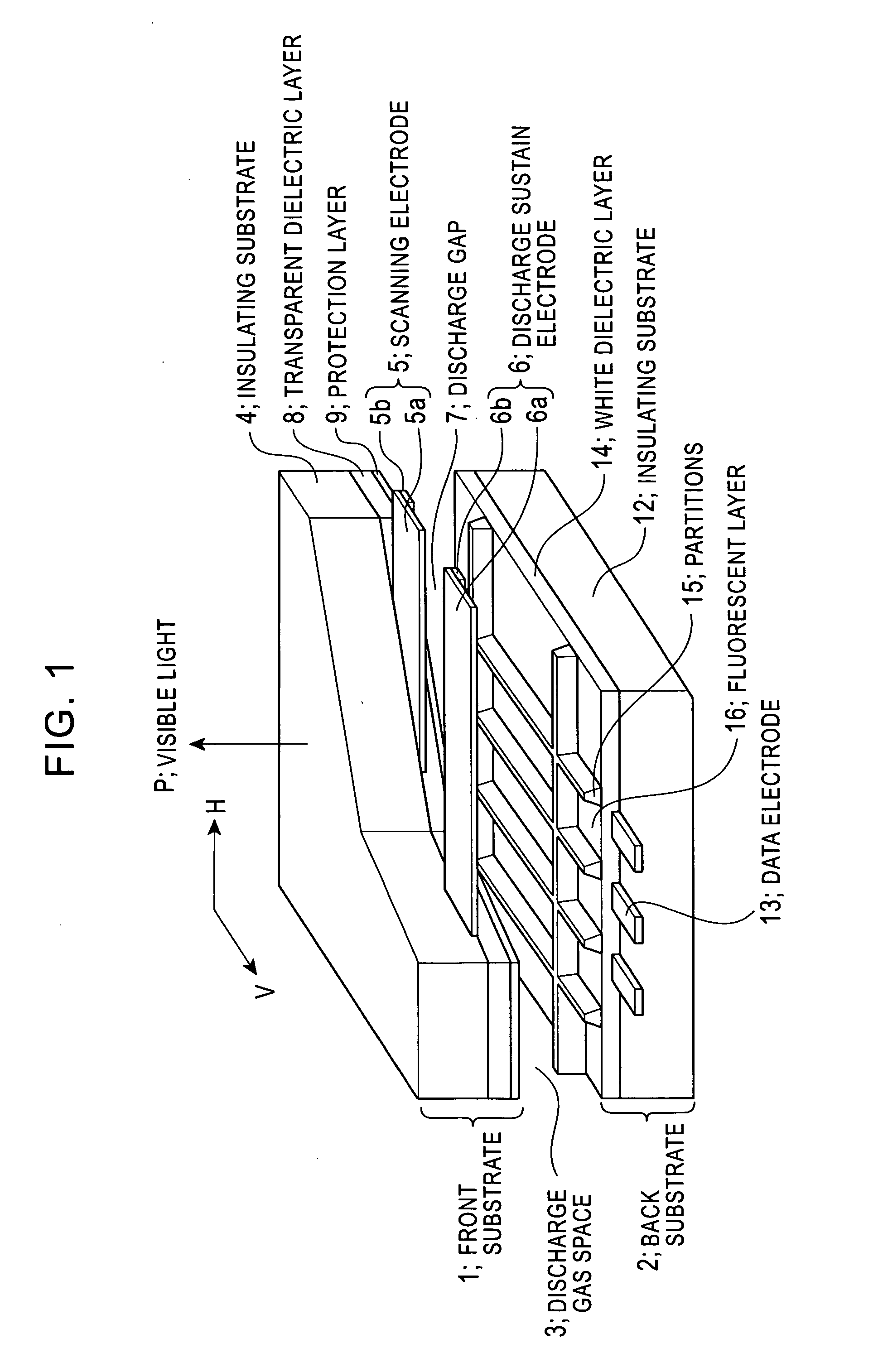
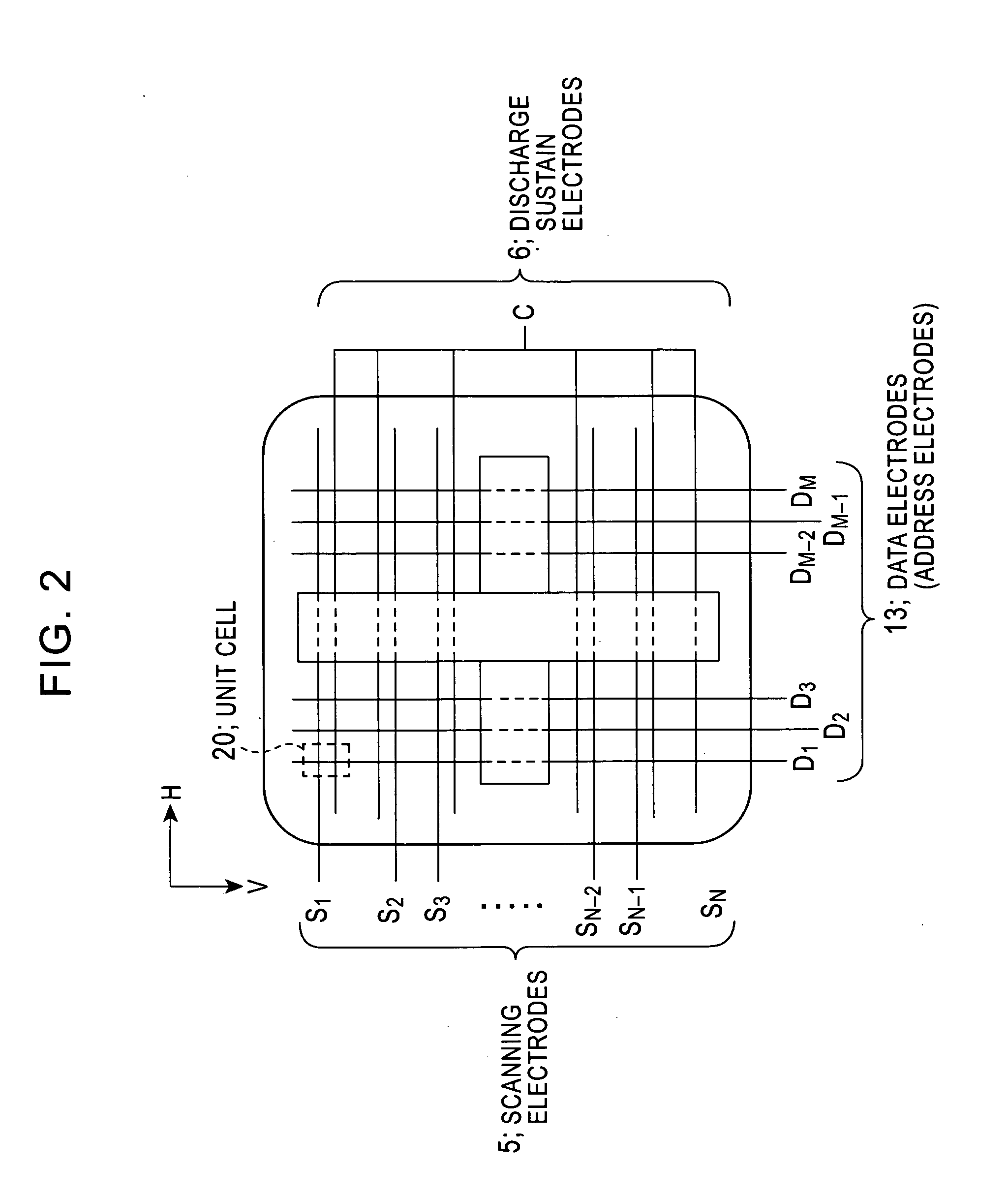
[0068] The PDP in this embodiment, as shown in FIG. 6, comprises a front substrate 21, a back substrate 22, a discharge gas space 23, scanning electrodes 25, discharge sustain electrodes 26, a discharge gap 27, data electrodes 33, partitions 35, large sub-cells 37, and small sub-cells 38. The front substrate 21 and back substrate 22 are disposed opposite to each other. The scanning electrodes 25 and discharge sustain electrodes 26 are disposed on a surface of the front substrate 21 opposite to the back substrate 22, and face each other across the discharge gap 27 of a predetermined width to make up surface discharge electrode pairs. The scanning electrode 25 is composed of a transparent electrode 25a and a bus electrode 25b. The bus electrode 25b is made of a metal material such as Al (aluminum), Cu (copper), Ag (...


PUM


Abstract

A plasma display device which has sufficient levels of gradation for displaying a dark image, and a sufficiently low display luminance for a black level. A unit cell is composed of a large sub-cell 37 and a small sub-cell 38, and the luminance level of the small sub-cell 38 is set to 1 / 16, ⅛, ¼, or ½ from one sub-field to another, so that the gradation of a dark image is smoothly displayed. Also, since the light emission luminance is sufficiently reduced when black is displayed by producing a priming discharge in the small sub-cell 38, a satisfactory image is displayed.

Description

BACKGROUND OF THE INVENTION [0001] 1. Field of the Invention [0002] The present invention relates to a plasma display device and a driving method for use in the plasma display device, and more particularly, to a plasma display device and a driving method for use in the plasma display device, which are suitable for use in displaying the gradation of a dark image. [0003] 2. Description of the Related Art [0004] A plasma display device mainly including a plasma display panel (hereinafter called the “PDP”) has a lot of advantages over displays such as CRT (Cathode Ray Tube) and a liquid crystal display device which have been conventionally used in wide applications, including less flickering, a large display contrast ratio, a flat shape, the ability to display a large screen, a higher response speed, and the like. For this reason, the plasma display devices have been increasingly used in recent years as display devices such as public display devices, large-sized flat televisions, and th...

Claims


Application Information

Patent Timeline
Patent Type & Authority Applications(United States)
IPC IPC(8): G09G3/28G09G3/20G09G3/288G09G3/291G09G3/292G09G3/294G09G3/298H01J11/12H01J11/14H01J11/22H01J11/24H01J11/26H01J11/32H01J11/34H01J11/36
CPCG09G3/2074G09G3/2077G09G3/293G09G2320/0271G09G3/2986G09G2310/0218G09G2320/0238G09G3/294
Inventor FURUTANI, TAKASHI
Owner PIONEER CORP
Learn More