
Protocol and line-rate transparent WDM passive optical network

a passive optical network and line-rate technology, applied in multiplex communication, electrical equipment, wavelength-division multiplex systems, etc., can solve the problems of in-field power resources, difficult to realize a proper physical layer solution for a low-cost fiber-optic access network, and inability to large-scale deployment, etc., to achieve the effect of eliminating costly dfb laser diodes and level of symmetry

Inactive Publication Date: 2005-12-29
LUCENT TECH INC
View PDF11 Cites 18 Cited by
  • Summary
  • Abstract
  • Description
  • Claims
  • Application Information

AI Technical Summary

Benefits of technology

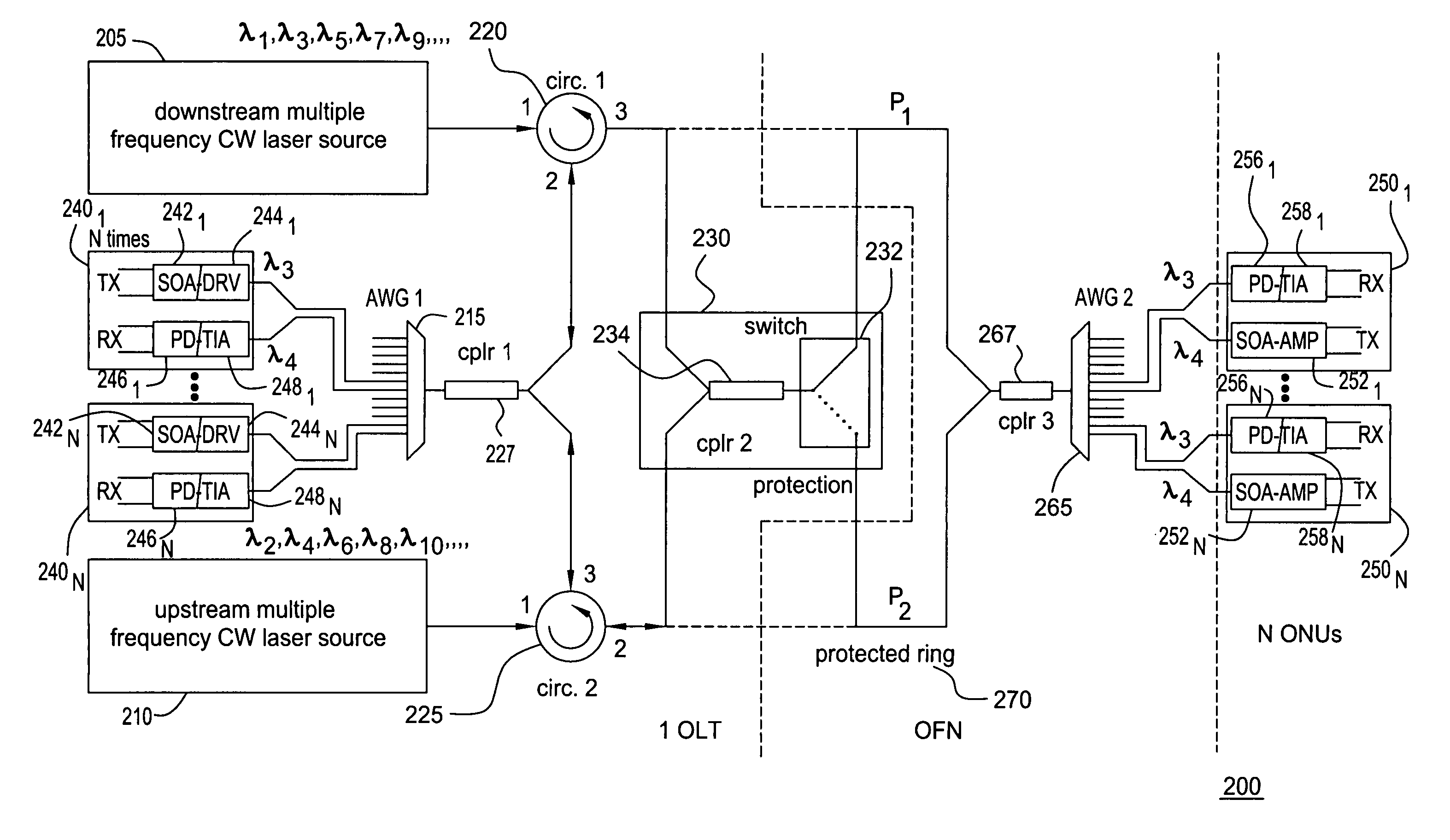
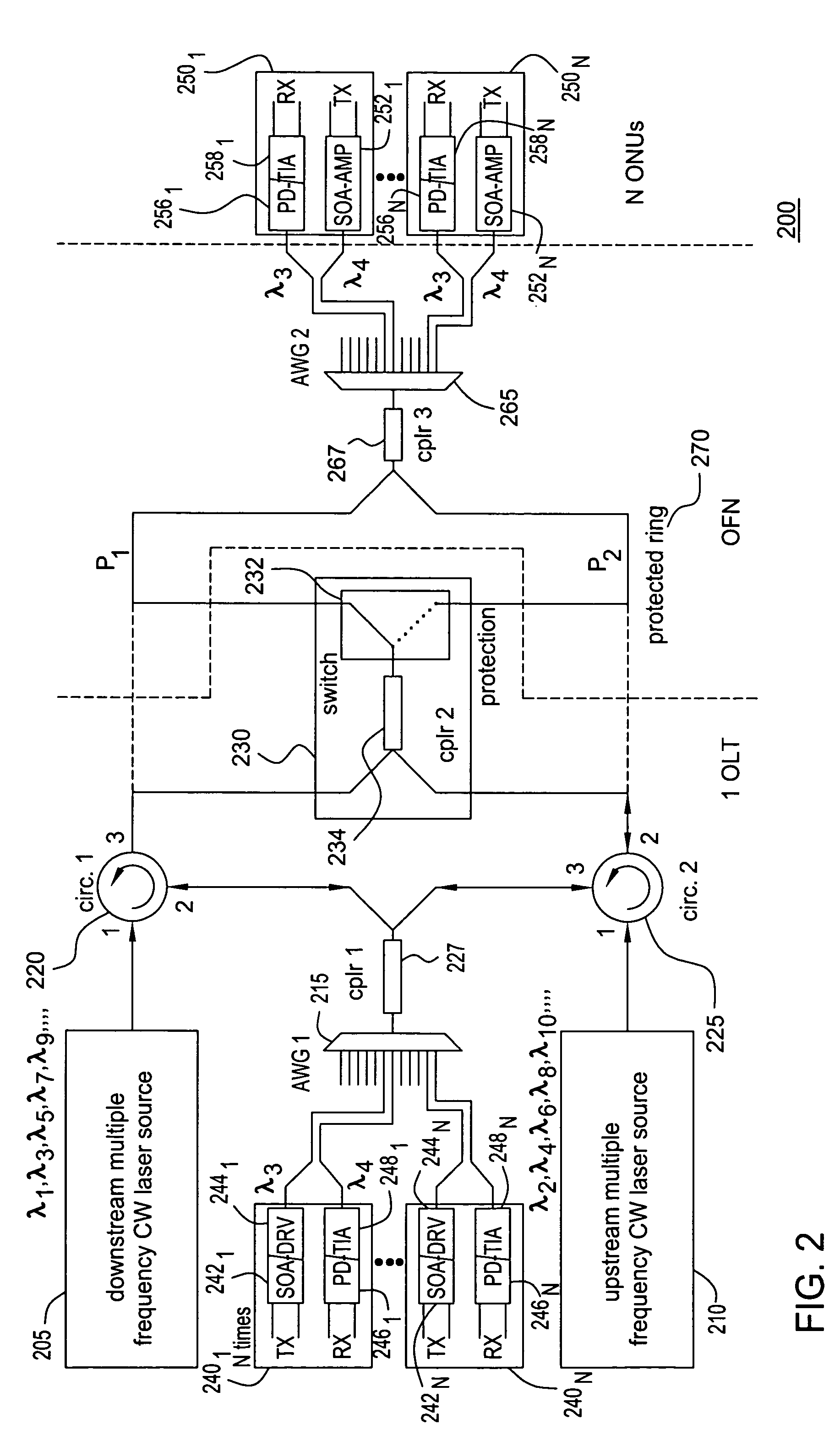
[0004] The present invention addresses various deficiencies of the prior art by providing a method, apparatus and system for a protocol and line-rate transparent WDM passive optical network architecture that scales in terms of bandwidth and number of optical network units (ONUs). The invention uses substantially the same reflective modulators both at the optical line terminal (OLT) and ONU sides to eliminate costly distributed feedback (DFB) laser diodes at the ONUs. Instead a single dual-output multiple-frequency laser source is located at the OLT side. In addition, due to the fact that both the OLT and the ONU of a WDM PON in accordance with the present invention have substantially the same reflective modulators and use substantially the same laser source, there exists a level of symmetry in the architecture. The ONUs of the protocol and line-rate transparent WDM passive optical network of the present invention each comprises a separate wavelength for communication.

Problems solved by technology

However cost issues do not allow for a large-scale deployment.
Such techniques, however, require in field power resources.
To this point, it has been shown difficult to realize a proper physical layer solution for a low cost fiber-optic access network.
Current solutions fall short because they are protocol sensitive, require expensive opto-electronic components and do not scale.

Method used


Image

  • Protocol and line-rate transparent WDM passive optical network
  • Protocol and line-rate transparent WDM passive optical network
  • Protocol and line-rate transparent WDM passive optical network

Examples


Embodiment Construction

[0017] The present invention advantageously provides a protocol and line-rate transparent WDM passive optical network (PON) architecture that scales in terms of bandwidth and number of ONUs. Both OLT and ONUs use reflective modulators to transmit any data. In various embodiments of the present invention, the reflective modulators are composed of a SOA having on one facet a pigtailed optical fiber and the other facet coated with a highly reflective coating. The ONUs of the protocol and line-rate transparent WDM PON each comprises a separate wavelength for communication. Although various embodiments of the present invention are described herein with respect to a protocol and line-rate transparent WDM passive optical network communicating via specific, illustrative protocols and using a specific number of wavelength channels, the specific embodiments of the present invention should not be treated as limiting the scope of the invention. It will be appreciated by those skilled in the art...


PUM


Abstract

The present invention provides a method, apparatus and system for a protocol and line-rate transparent WDM passive optical network architecture that scales in terms of bandwidth and number of ONUs. Both an included optical line terminal and each of a plurality of ONUs use substantially the same reflective modulators to modulate respective wavelength channels to impart data thereto. In various embodiments of the present invention, the reflective modulators are composed of a SOA having on one facet a pigtailed fiber and the other facet coated with a highly reflective coating. In the WDM passive optical network of the present invention, the ONUs each comprises a separate wavelength for communication in the upstream and the downstream directions. The present invention allows for all-passive components to be placed in the field, thus, requiring no power between a central office and a user or subscriber's premises.

Description

FIELD OF THE INVENTION [0001] This invention relates generally to the delivery of communication services to subscribers via a communication network and, more specifically, to the transmission of optical signals to individual subscribers or groups of subscribers over a protocol and line-rate transparent WDM passive optical network. BACKGROUND OF THE INVENTION [0002] Fiber-to-the-home broadband-access is becoming increasingly popular. Such high capacity communication links provide broadband transmission access capable of reaching all the way to the individual subscribers of a communication network. Known technologies and techniques like classic passive optical networks are standardized in full-service access networks (FSAN). However cost issues do not allow for a large-scale deployment. [0003] Different architectures employ point-to-point transmission and perform opto-electronic conversions to aggregate traffic where electro-optic conversion takes place to transmit to the next point o...

Claims


Application Information

Patent Timeline
Patent Type & Authority Applications(United States)
IPC IPC(8): H04B10/00H04J14/02
CPCH04J14/0226H04J14/0227H04J14/0282H04J14/0291H04J2014/0253H04J14/0246H04J14/0247H04J14/0252H04J14/0232
Inventor JENNEN, JEAN G.SMETS, ROBERT
Owner LUCENT TECH INC
Learn More