
Method and apparatus for placing a timestamp in a frame

Active Publication Date: 2005-12-29
SPIRENT COMM
View PDF6 Cites 99 Cited by
  • Summary
  • Abstract
  • Description
  • Claims
  • Application Information

AI Technical Summary

Benefits of technology

[0022] Accordingly, it is a primary object of the present invention to provide a method and apparatus that can place timestamp information into a portion of a frame during frame layer processing wherein timestamp information is embedded into such portion subsequently to processing of such portion at an upper protocol layer and further subsequently to the computation of an error detection code for the packet including such portion at a lower protocol layer. It is a further object of the present invention to provide such method and apparatus wherein as many such frames as possible are capable of being transmitted continuously over a period of time, with the current timestamp information placed into each frame, such that upper layer latency measurements provide the broadest coverage and meaning in real time network traffic environments. It is a yet a further object of the present invention to provide such method and apparatus wherein the frame includes timestamp information in the Layer 7 message portion.
[0024] A feature of the present invention is that the timestamp signature is embedded with initialized data during processing at an upper protocol layer so that processing at a lower protocol layer, whereat the error detection code is computed, can be performed using normal protocol specifications, procedures and formats. This feature advantageously allows packets to be processed normally through all protocol layers up to the time timestamp information is placed into the frame during frame layer processing obviating any degradation of the ability of a test instrument to develop a sufficient number or transmission rate of timestamp containing packets.
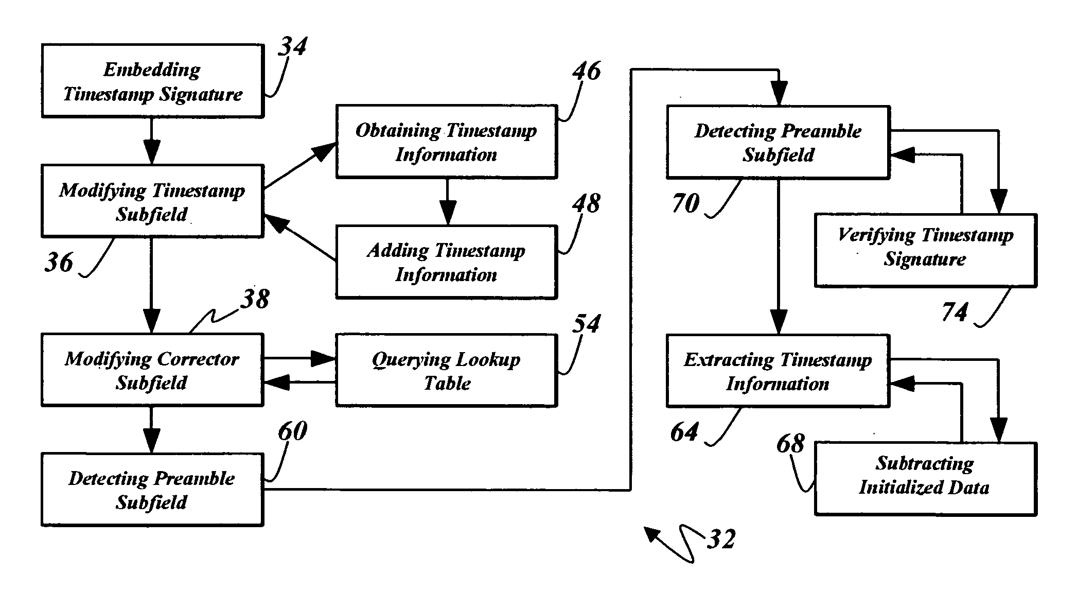
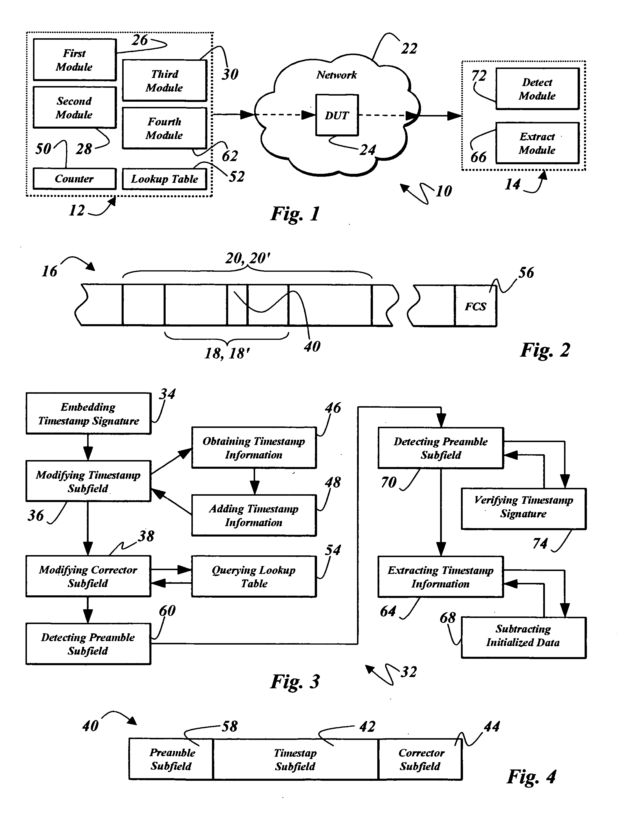
[0025] Another feature of the present invention is that the initialized data within the timestamp subfield of the timestamp signature can be modified with timestamp information during frame layer processing subsequently to processing at the upper and lower protocol layers and any other protocol layer at which processing occurs prior to modification of the initialized data. This feature advantageously allows processing of a timestamp containing packet to occur over several protocol layers without the inherent latency of processing times for these layers being included into the timestamp information. In one particular aspect of the present invention, the modification may occur upon imminent transmission of the frame such that any inherent latency is advantageously highly deterministic, and therefore easily correctable or compensated for, or even negligible in the context of the latency measurements to be obtained.
[0026] Yet another feature of the present invention is that the timestamp signature includes a readily modifiable corrector subfield to ensure that the error detection code computed during processing of the packet at the lower protocol layer remains valid by ensuring that a functionally equivalent constant determinable from the initialized data in the first and corrector subfields and the modified data in each of these subfields remains unchanged after modification. For example, in one aspect of the present invention, the modification of the data in the corrector subfield can be accomplished by obtaining the data for this subfield from a lookup table, thereby advantageously eliminating any further processing to compute such modified data, thereby further minimizing inherent latency between placing of the timestamp and transmission of the frame.

Problems solved by technology

However, the functional specifications for the packet in which timestamp information is to be inserted, including the format and content of various fields therein required for compatibility with the networking framework of the network for which latency measurements are being obtained, are generally not amenable to the direct insertion of timestamp information into the packet upon its imminent transmission into the network.
Since the error detection code cannot be computed until after the data portion has been generated, as well as any other header information, there is an inherent latency within the transmitting device between obtaining the timestamp information and encapsulating the packet at the present protocol layer.
Furthermore, the timestamp information may have been required to be inserted into a data portion of the packet when being processed at a higher protocol layer, prior to the error detection code for the packet being computed at the present protocol layer, thereby resulting in yet greater latency between insertion of timestamp information into the packet and computation of the error detection code.
Therefore, the inherent latency within the transmitting device is indeterminate since it cannot be accurately determined due to unknown processing times at each of the protocol layers subsequent to inserting timestamp information into the packet and processor interrupts occurring during such processing.
Accordingly, without any precise correction for the latency between obtaining the timestamp information and the actual time of transmission being possible, the network latency measurement, wherein a test instrument generates and transmits frames using timestamp containing packets as above described, timestamp information retrieved at a receiving test instrument inherently includes this indeterminate term and therefore does not accurately determine the true latency of the network.
However, when testing higher layer protocols, and devices that are sensitive to those protocols, the insertion of the binary formatted fields is not generally viable.
Insertion of a binary-formatted field within this Layer 7 message portion would corrupt the HTTP messages, resulting in a high probability that the HTTP message would be dropped by devices under test that are cognizant of the HTTP protocol and need to interpret the HTTP messages during Layer 7 processing upon receipt.
However, one significant disadvantage and limitation of each of these four techniques of embedding the ASCII timestamp during Layer 7 processing is that timestamp information must be inserted by the Layer 7 application in the test instrument, or transmitting device, into the ASCII message portion of the packet prior to passing the message to the next lower layer in the protocol stack and ultimately to the Layer 2 process that frames the resultant packet and transmits such frame.
As described generally above, there can be a significant, indeterminate and uncontrolled latency in the protocol stack of the transmitting device from the time the timestamp is inserted during Layer 7 processing and the time the frame actually exits the test instrument.
This test instrument latency, for example on the order of 10 ms, can be significant in terms of the link speed or of total network traversal time, and can thus render the latency measurements that are being attempted as unreliable or even meaningless.
Another significant disadvantage and limitation of each of these four techniques of embedding the ASCII timestamp during Layer 7 processing is that timestamp information is obtained prior to calculation of the Layer 4 checksum for the Layer 4 header that encapsulates the packet.

Method used


Image

  • Method and apparatus for placing a timestamp in a frame
  • Method and apparatus for placing a timestamp in a frame

Examples


Embodiment Construction

[0032] Referring now to FIG. 1, there is shown a system 10 including a transmitting device 12 and a receiving device 14. With further reference to FIG. 2, the transmitting device 12 is operable in a conventional and known manner to process and transmit frames, such as frame 16, and the receiving device 14 is operable to receive and process such frames, also in a conventional and known manner.

[0033] Exemplarily as described above, such frames result from processing information at each protocol layer of a protocol stack in the transmitting device 12. For example, the frame 16 includes a first portion 18 and a second portion 20, wherein the first portion 18 is contained within the second portion 20. The first portion 18 is processable at a selected protocol layer of the protocol stack. The second portion 20 is processable at a lower protocol layer of the protocol stack subsequently to the processing of the first portion 18. The processing of the second portion 20 may exemplarily inclu...


PUM


Abstract

Timestamp information can be placed in a frame that includes a first portion processable at a selected layer of a protocol stack and a second portion processable at a lower protocol layer of the protocol stack subsequently to the processing of the first portion, wherein the first portion is contained within the second portion and wherein a numerically computed error detection code for the second portion is computed during processing of the second portion. A timestamp signature having a timestamp subfield of initialized data and a corrector subfield of initialized data is embedded in the first portion during processing thereof at the selected protocol layer. A numerical constant functionally equivalent to the numerically computed error detection code is determinable from the initialized data in the timestamp subfield and the corrector subfield. The data in said timestamp subfield is modified with timestamp information subsequently to processing of the second portion at the lower protocol layer. The data in the corrector subfield is then modified such that the numerical constant as determinable from the modified data in the timestamp subfield and the corrector subfield remains unchanged, whereby the numerically computed error detection code computed at the lower protocol layer remains valid.

Description

BACKGROUND OF THE INVENTION [0001] 1. Field of the Invention [0002] The present invention is directed generally to the placing of a timestamp in a frame to be transmitted and, more particularly, in a portion of the frame that has been processed at a selected protocol layer of a protocol stack and also processed subsequently at another layer of the protocol stack whereat an error detection code for such portion is computed prior to placing the timestamp in such portion. [0003] 2. Description of the Related Art [0004] In the monitoring, testing and maintenance of packet switched networks, it is necessary to measure accurately one or more measures of network latency, for example, the time it takes for a packet to traverse the network from its source to its destination. To measure this traversal time, various apparatus and methods have been developed in the prior art that share a basic concept of placing a timestamp, also referred to herein as timestamp information, into one or more pac...

Claims


Application Information

Patent Timeline
IPC IPC(8): H04J3/06H04L12/26
CPCH04L43/106H04L43/0852
Inventor HATLEY, WILLIAM T.CHUA, ROY LIANG
Owner SPIRENT COMM
Learn More