
PTFE stud for ultrahigh-value resistor and method therefor

a technology of polytetrafluoroethylene and resistor, which is applied in the direction of coupling contact members, fixed connections, relays, etc., can solve the problems of internal structure susceptible to thermal stress, resistance instability, and resistance error, so as to prevent thermal shock from being applied, simplify the assembly process, and prevent thermal shock

Inactive Publication Date: 2005-12-29
AGILENT TECH INC
View PDF8 Cites 0 Cited by
  • Summary
  • Abstract
  • Description
  • Claims
  • Application Information

AI Technical Summary

Benefits of technology

The present invention provides a PTFE stud and a method for attaching an ultrahigh-value resistor to a substrate without soldering. The PTFE stud has a first portion that is mounted on the substrate and a second portion that is attached to the first portion and not in contact with the substrate. The first portion is made of insulating material, while the second portion has a mounting hole and a groove for wiring. The PTFE stud allows for air wiring and simplifies the assembly process. It also prevents thermal shock from being applied to the ultrahigh-value resistor and reduces the manufacturing cost of the first portion. The technical effects of the invention include reducing the risk of instability in the resistance of the ultrahigh-value resistor and simplifying the assembly process.

Problems solved by technology

Resistance errors may be caused by, for example, temperature changes.
Those ultrahigh-value resistors have an internal structure that is susceptible to thermal stress.
Thus, when the ultrahigh-value resistors are mounted by soldering, a shock due to the soldering-induced heat, i.e., thermal stress applied in a short period of time, may render the resistance unstable.
However, the method for mitigating thermal shock by attaching the above-noted heat-dissipating jig has problems in that, for example, the process and procedure for mounting a component become complicated and subsequent maintenance work does not allow soldering.
The above-noted stud product using PTFE material requires high insulation between the substrate and the terminal and is not adapted to reduce thermal transmission.
Document 1, however, does not disclose a technique for reducing thermal transmission.

Method used


Image

  • PTFE stud for ultrahigh-value resistor and method therefor
  • PTFE stud for ultrahigh-value resistor and method therefor
  • PTFE stud for ultrahigh-value resistor and method therefor

Examples


Embodiment Construction

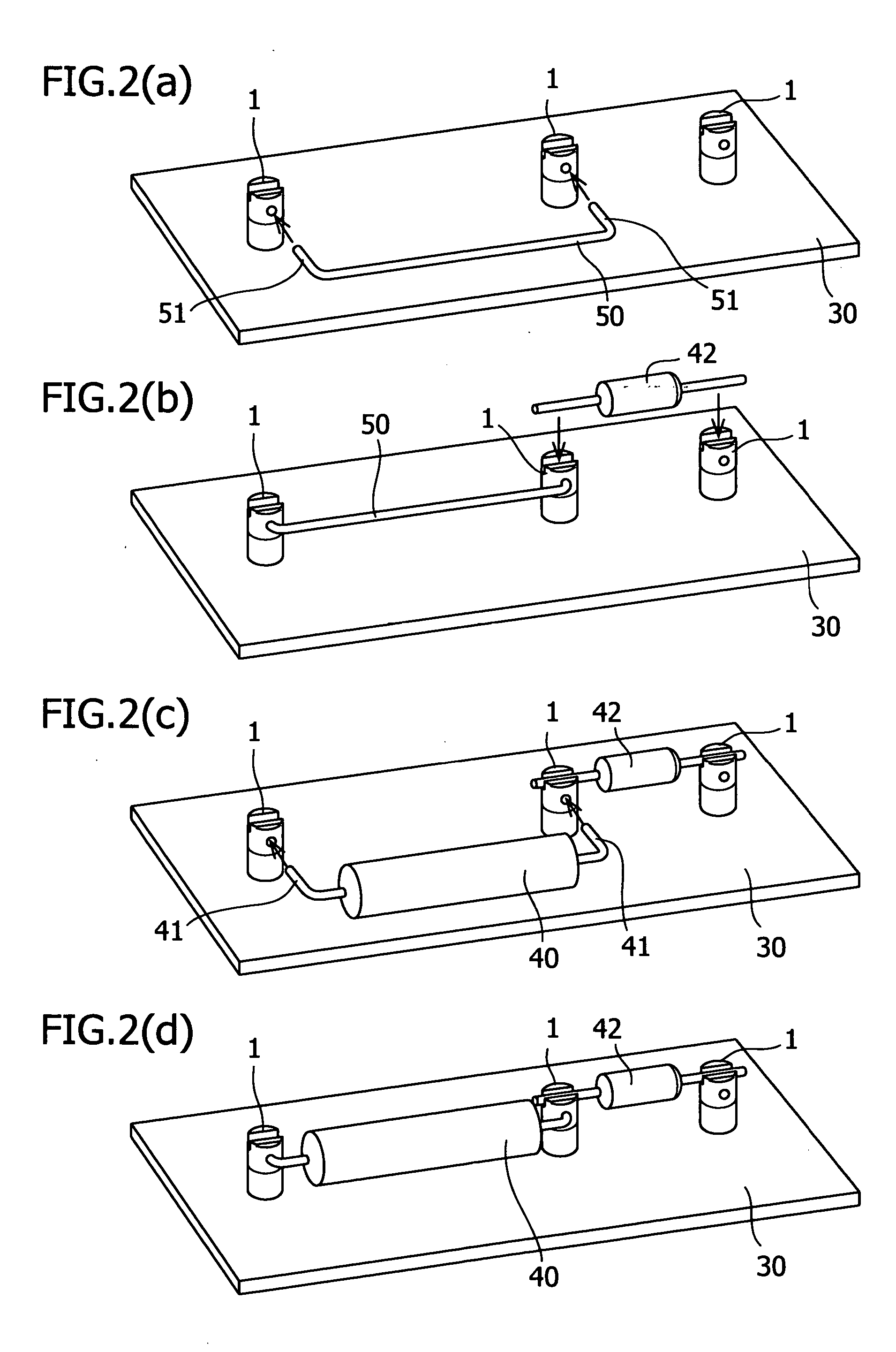
[0021] A PTFE (polytetrafluoroethylene) stud according to an embodiment of the present invention will be described below with reference to FIGS. 1A to 1C and 2A to 2D. FIG. 1A is a front view of a PTFE stud according to the present invention, FIG. 1B is a side view thereof, and FIG. 1C is a top view thereof. FIGS. 2A to 2D show processes for mounting PTFE studs on a substrate and then attaching an ultrahigh-value resistor to the PTFE studs.

[0022] As shown in FIGS. 1A to 1C, a PTFE stud 1 is formed to have a substantially-cylindrical shape along a central axis 2 and is constituted by a first portion 10 formed of PTFE material and a second portion 20 formed of brass. The first portion 10 and the second portion 20 have a face 10a and a face 20a, respectively, which are perpendicular to the central axis 2. The first portion 10 and the second portion 20 are separated from each other at the faces 10a and 20a and are combined together such that the faces 10a and 20a are in contact with ea...


PUM


Abstract

A PTFE stud for an ultrahigh-value resistor includes a first portion to be mounted on a substrate and a second portion attached to the first portion so as to not be in contact with the surface of the substrate. The first portion is formed of insulating material and the second portion has a mounting hole that penetrates the second portion so as to be parallel to the surface of the substrate. The mounting hole is adapted such that the lead of the ultrahigh-value resistor is inserted thereinto. The ultrahigh-value resistor can be mounted without soldering.

Description

BACKGROUND OF THE INVENTION [0001] 1. Field of the Invention [0002] The present invention relates to a polytetrafluoroethylene (PTFE) stud for mounting an ultrahigh-value resistor whose characteristics may change due to soldering-induced heat. [0003] 2. Description of the Related Art [0004] Ultrahigh-value resistors typically have a resistance of several giga-ohms to several tera-ohms. Known examples include what is disclosed in http: / / www.hydrazine.co.jp / e_c / pdf / j-pdf / j-rh-u.pdf and http: / / www.hydrazine.co.jp / e_c / pdf / j-pdf / j-ru.pdf found at http: / / www.hydrazine.co.jp / e_c / jpn / j_teiko.html. [0005] Those ultrahigh-value resistors are used for, for example, a measuring instrument to detect a micro current. Resistance errors have a large influence on the measurement accuracy. Resistance errors may be caused by, for example, temperature changes. Those ultrahigh-value resistors have an internal structure that is susceptible to thermal stress. Thus, when the ultrahigh-value resistors are m...

Claims


Application Information

Patent Timeline
Patent Type & Authority Applications(United States)
IPC IPC(8): H01R4/70H01R13/33
CPCH01R13/33H01R9/091H01R12/57
Inventor SHIOBARA, SYUNSUKEMATSUDA, CHIKAO
Owner AGILENT TECH INC
Learn More