
Asymmetrical thermodynamic cycle and engine to implement it

a technology of thermodynamic cycle and muffler, which is applied in the direction of machines/engines, mechanical equipment, valve drives, etc., can solve the problems of reducing the efficiency of the engine, and detonating fuel, so as to reduce the loss of power in the muffling process, reduce the level of pollution, and reduce the effect of fuel consumption

Inactive Publication Date: 2005-12-29
SHERMAN VICTOR L
View PDF4 Cites 19 Cited by
  • Summary
  • Abstract
  • Description
  • Claims
  • Application Information

AI Technical Summary

Benefits of technology

[0015] The devices in group (a) allow part of the air taken in during the intake stroke to escape during the compression stroke through the still open intake / exhaust valve(s) until the amount of air left in the cylinder is exactly enough for the consumption of all of the fuel to be injected to the cylinder at the particular throttle setting. After reaching this point, the valve(s) close, compression begins and the fuel is actually injected into the cylinder. But used only by themselves, these devices (in group a) reduce the compression ratio at which ignition is being initiated, thus reducing the efficiency of the engine.
[0017] The devices of the group (c) tune the combustion chamber to the particular octane of the fuel by setting the position of conditioning piston. Only the unique combination of variable compression stroke and variable effective volume of combustion chamber(s) both controlled in dependence of the amount of fuel fed to keep the compression ratio permanent, conditions the engine for extracting more power from the same amount of fuel used (or using less fuel for the same power delivered). As a result, fuel consumption is reduced.
[0018] Because of more complete combustion, the level of pollution is reduced too. In addition, since exhaust gases in the inventive engine leave the cylinders at substantially lower pressure and temperature, the losses of power in the process of muffling, are also reduced.

Problems solved by technology

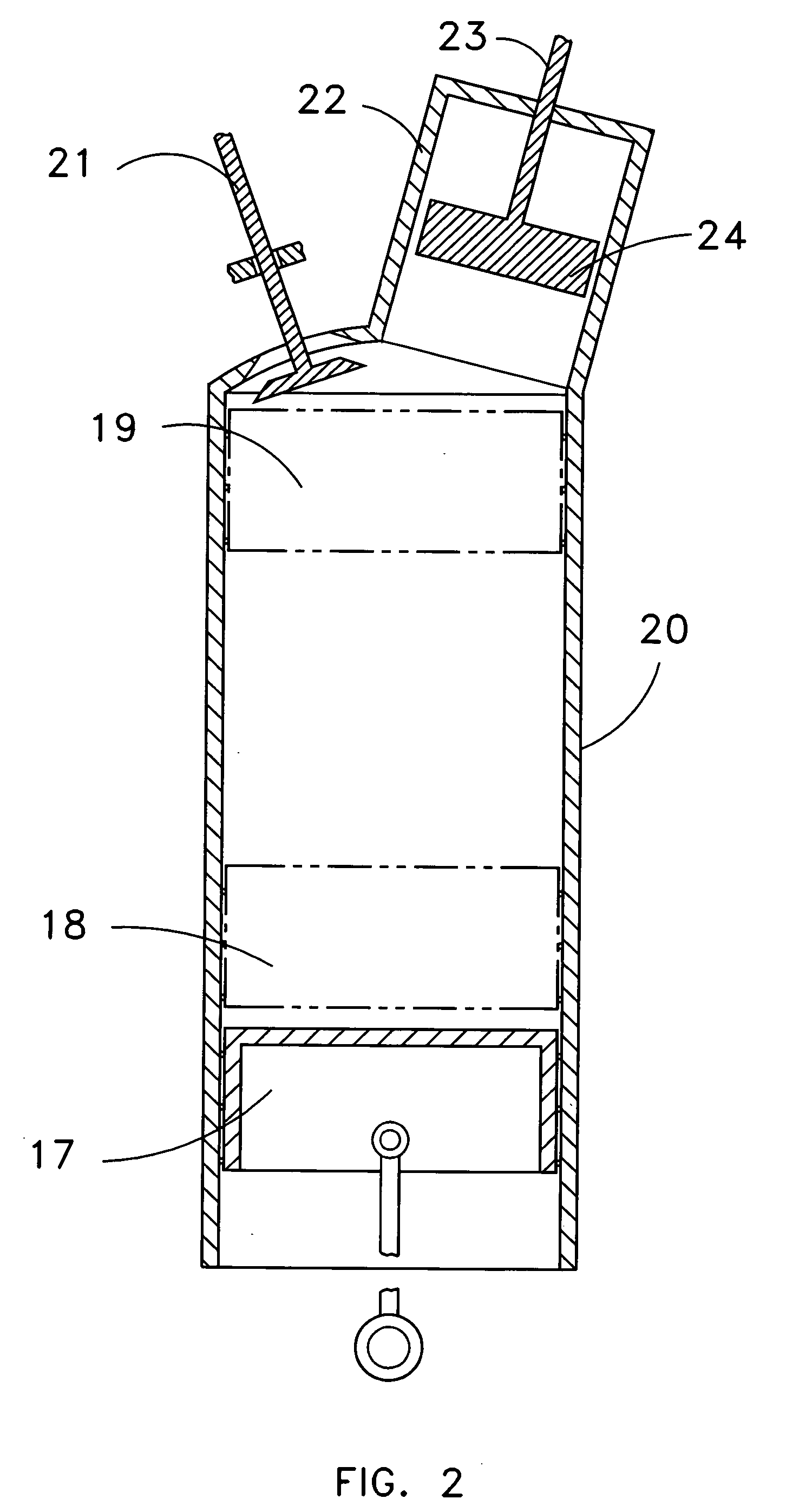
But used only by themselves, these devices (in group a) reduce the compression ratio at which ignition is being initiated, thus reducing the efficiency of the engine.
But by themselves, if not combined with adjustment of the beginning of compression, the movements of the conditioning piston change the compression ratio, either reducing the efficiency of the engine, or causing detonation of the fuel.

Method used


Image

  • Asymmetrical thermodynamic cycle and engine to implement it
  • Asymmetrical thermodynamic cycle and engine to implement it
  • Asymmetrical thermodynamic cycle and engine to implement it

Examples


Embodiment Construction

[0024] The inventive method of achieving complete combustion of fuel and oxygen within engine's cylinders is explained in the pressure-volume diagram in FIG. 1. The diagram shows three pressure-volume function curves at three different throttle settings. The low throttle process curve is described by the line beginning at the idle portion of the compression stroke 10, progressing to the beginning of the active portion of the compression stroke 9, to the peak of the compression stroke and the point of minimum volume of the mixture prior to ignition 14, to the point of, maximum pressure of the power stroke 1, through the point on the power stroke at which the combustion gases have expanded to the volume of the air originally compressed 11, to the end of the power stroke 6. The intermediate throttle process curve is described by the line beginning at the idle portion of the compression stroke 10, progressing to the beginning of the active portion of the compression stroke 8, to the pea...


PUM


Abstract

A method and device for achieving complete combustion and greater efficiency throughout a broad range of power outputs in a four-stroke internal combustion engine intended for use mostly at sea level by providing a means of controlling the amount of air to be compressed in a fixed ratio to the amount of fuel to be injected together with a means of controlling of the volume to which the fuel-to-air mixture is to be compressed prior to ignition in a fixed optimum ratio to the volume of air taken in with an ability to use different octane fuels and a power stroke that is always longer than the adjusted compression stroke in order to yield greater work output at lower exhaust pressure than engines designed for equal compression and power stroke operation. This reduces fuel consumption, noise and pollution and improves total engine efficiency to 35-40%.

Description

TECHNICAL FIELD [0001] The present invention relates to improvements in 4-stroke internal combustion engines (gasoline, diesel, etc.) used for transportation, generation of energy, or powering of different mechanisms. BACKGROUND ART [0002] Internal combustion engines to which the present invention is related are based mostly on Otto or Diesel thermodynamic cycles, or on their variations. These engines are widely described in literature. They are inexpensive, have high power-to-weight ratios, and are relatively economical. But their efficiency is still substantially less than the thermodynamically possible theoretical limit. [0003] One of their problems is that the length of the compression stroke is equal to the length of the power stroke. Therefore, the gases during the power stroke (which obviously have higher pressure) cannot expand enough to expend all of their energy within the cylinder. As a result, they exhaust at too high a pressure, so that their energy is not fully utilize...

Claims


Application Information

Patent Timeline
IPC IPC(8): F01L1/08F01L1/34F01L13/00F02B69/02F02B75/02F02B75/04
CPCF01L1/08F01L1/146F02B75/042F01L13/0063F02B69/02F01L1/181F01L2305/00
Inventor SHERMAN, VICTOR L.
Owner SHERMAN VICTOR L
Learn More