
Device and method for fastening structural members

Inactive Publication Date: 2005-12-22
ORCHARD BRIAN
View PDF25 Cites 38 Cited by
  • Summary
  • Abstract
  • Description
  • Claims
  • Application Information

AI Technical Summary

Benefits of technology

[0007] The present invention advantageously provides a simple, efficient, flexible and easy way of fastening structural members together. The present device permits driving fasteners in a consistent manner resulting in a join between structural members in which the fastener is less visible and the join less susceptible to infiltration by water. Since the jig bodies of the device are affixed to a base plate, there are no moving parts to wear out or to cause difficulties in operation in use.
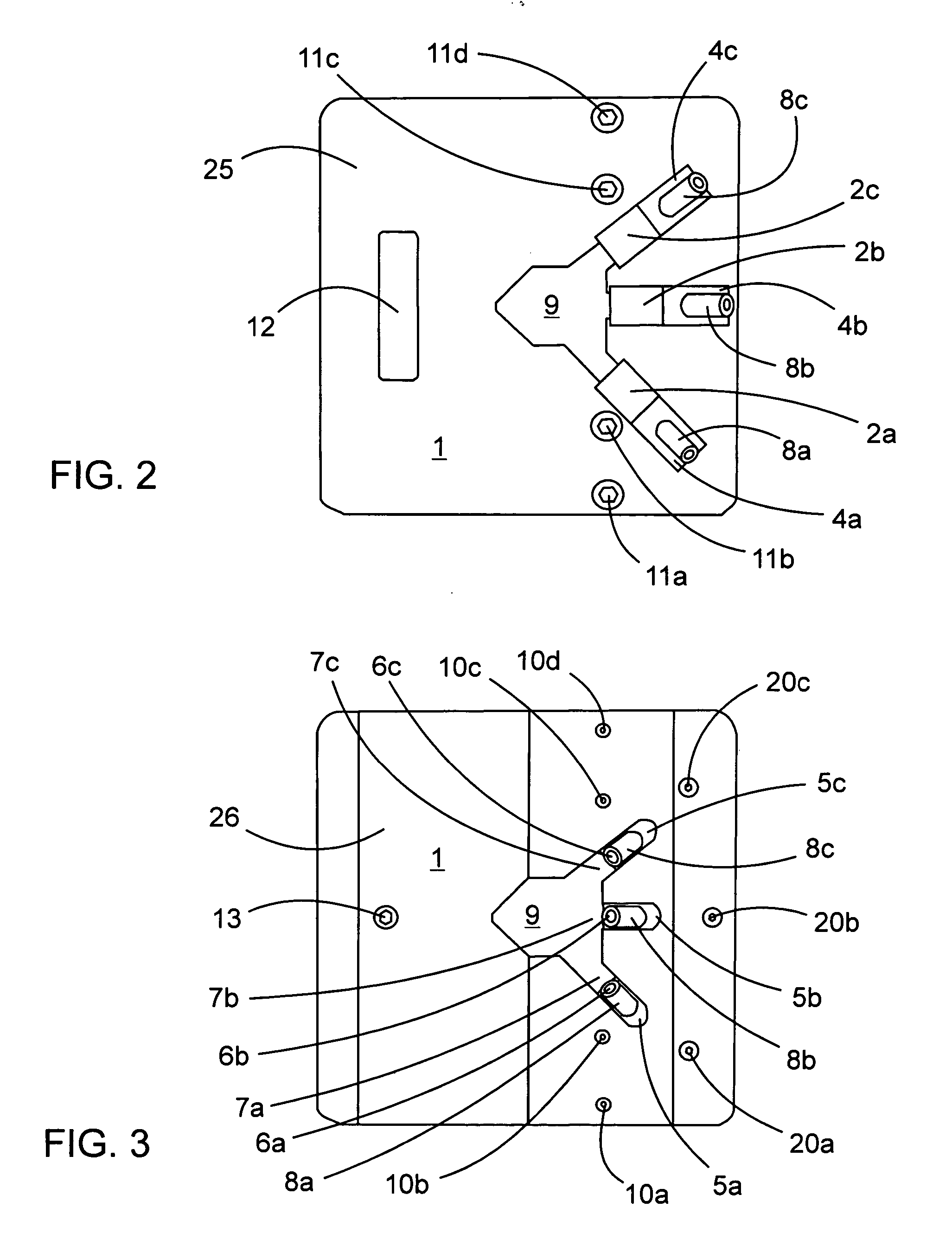
[0012] To facilitate proper placement of the device on the first structural members, the base plate further may have a viewing window therethrough. The viewing window is positioned forward of the bottoms of the angled bores to permit visualization of the side face of the structural member through which the fastener is to be driven. As indicated above, the bottom of each angled bore is in communication with an aperture in the base plate. Each angled bore may be associated with its own separate aperture. Alternatively, two or more of the apertures may form a single larger opening in the base plate. In one embodiment, the viewing window and the apertures together form one continuous opening in the base plate.
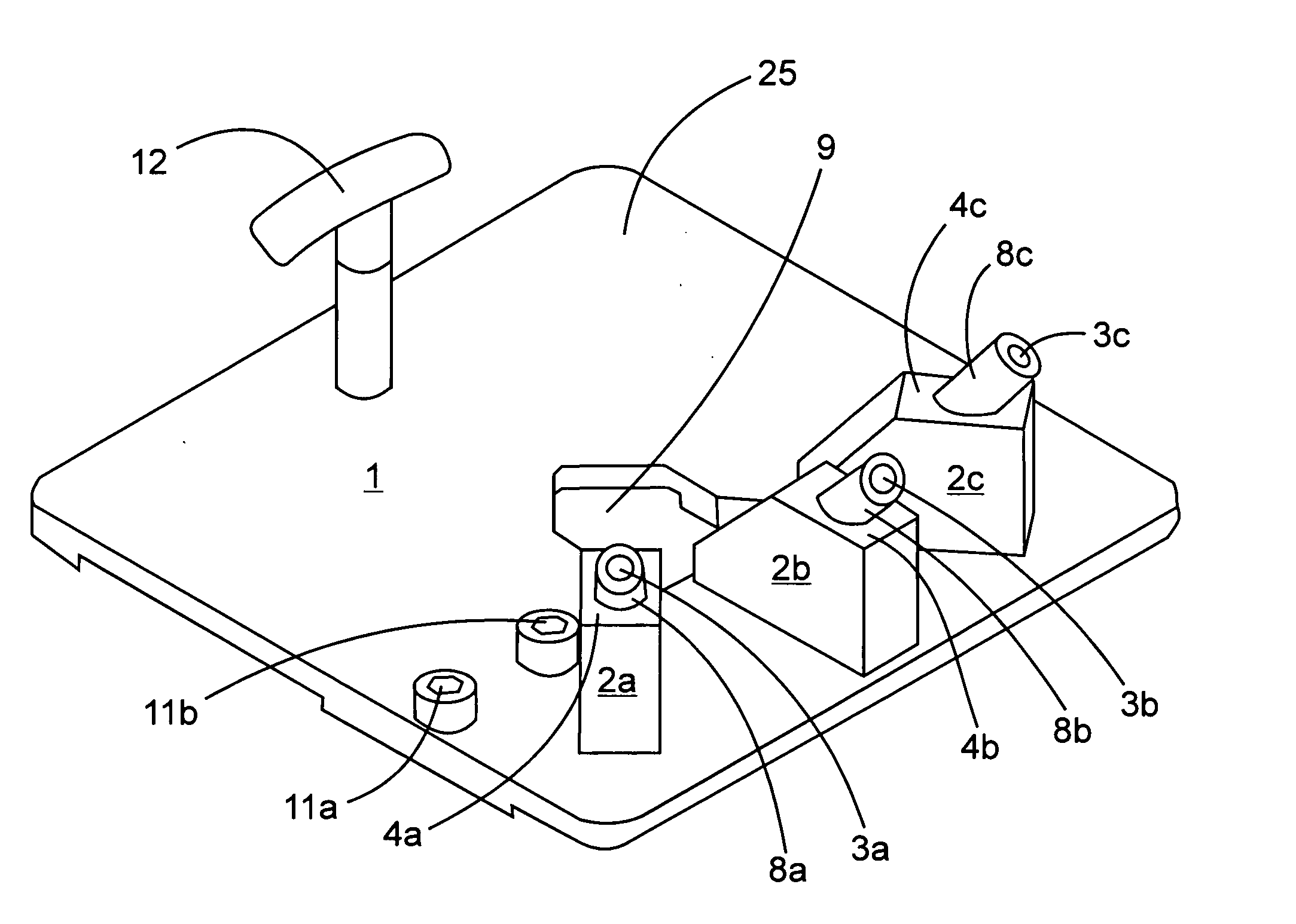
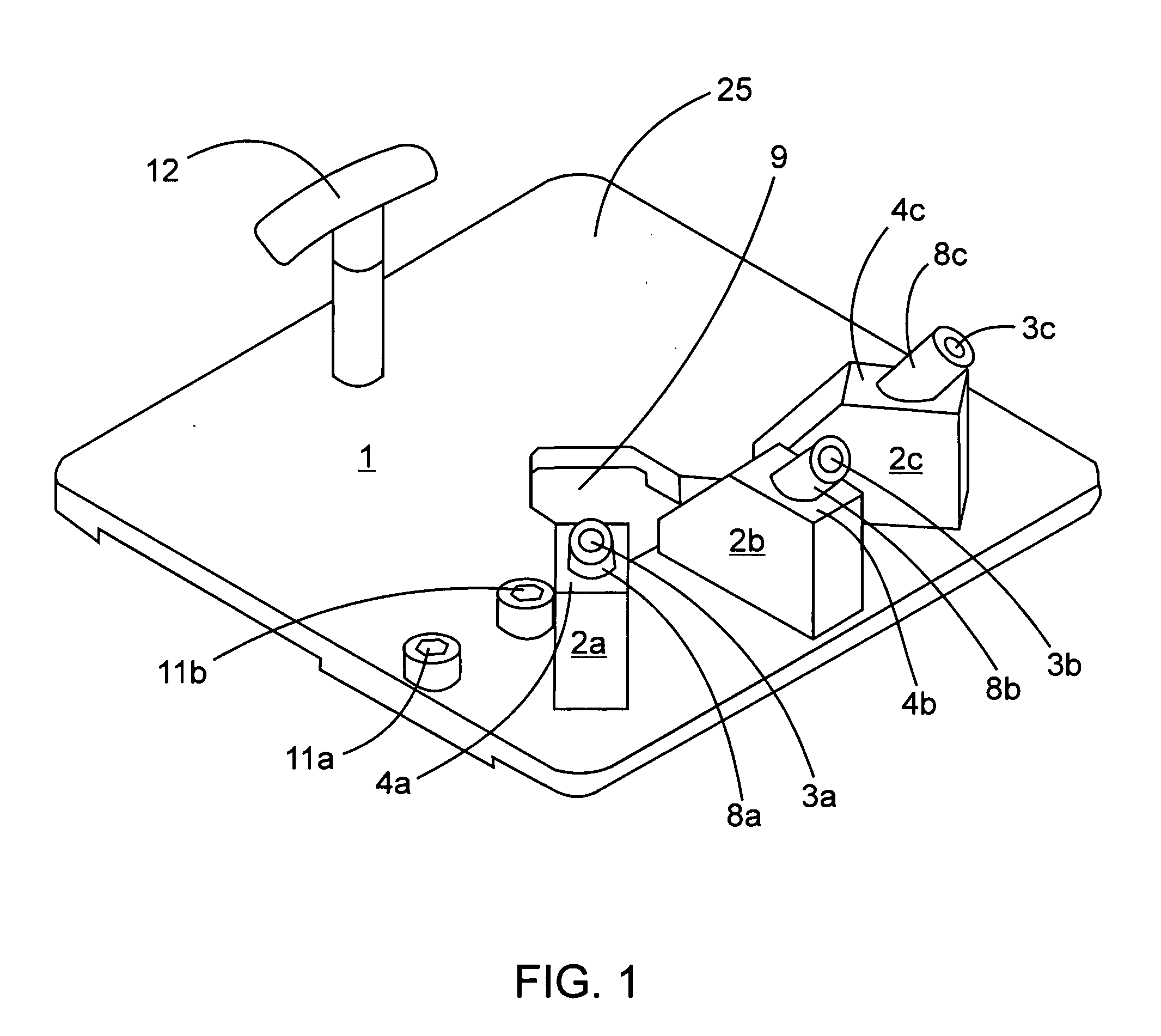
[0014] The device may further comprise a handle affixed atop the base plate. A handle is advantageous for carrying the device and setting it in the proper location on the structural members. In a preferred embodiment, the handle is T-shaped having a single post perpendicular to the base plate and topped by a horizontal gripping member. In another preferred embodiment, the handle has an inverted U-shape having two spaced apart posts each perpendicular to the base plate and connected by a horizontal gripping member.

Problems solved by technology

This method results in fasteners which are visible and exposed to the weather.
Visible fasteners are unsightly and exposure to weather, particularly moisture, can lead to infiltration of moisture.
Infiltration of moisture can lead to premature cracking and rotting of the deck.

Method used


Image

  • Device and method for fastening structural members
  • Device and method for fastening structural members
  • Device and method for fastening structural members

Examples


Embodiment Construction

[0026] Referring to FIGS. 1-5, a device of one embodiment of the present invention is depicted. A base plate I having a top surface 25 and a bottom surface 26 is provided having three jig bodies 2a, 2b, 2c affixed on the top surface 25 by bolts 20a,20b,20c from underneath the base plate 1. The bolts 20a,20b,20c may be countersunk into the bottom surface 26 of the base plate 1 and are threaded into mating connectors (one shown at 21b in FIG. 5) which are countersunk into the underside of the jig bodies. The jig bodies have angled bores 3a,3b,3c passing therethrough from top faces 4a,4b,4c to bottom faces 5a,5b,5c of the jig bodies at an angle of 50 degrees with respect to the bottom surface 26 of the base plate 1. The angled bores have bottoms 6a,6b,6c in communication with respective apertures 7a,7b,7c in the base plate 1. The bottoms 6a,6b,6c of the angled bores 3a,3b,3c are positioned to substantially form a line. One of the jig bodies 2a is oriented to permit driving a fastener a...


PUM

PropertyMeasurementUnit
Angleaaaaaaaaaa
Angleaaaaaaaaaa
Angleaaaaaaaaaa

Abstract

The present invention provides a device and method for fastening structural members, particularly for fastening a deck member to a deck joist. The device and method provide the ability to affix fasteners in a manner which reduces their visibility on the deck and which reduces the occurrence of moisture infiltration around the fastener. The device has a base plate having at least two bores therethrough and at least two jig bodies affixed in different orientations atop the base plate, each of the jig bodies having an angled bore, the angled bores in communication with a respective one of the base plate bores, at least one of the bottom ends of the angled bores in communication with a space between a pair of deck members, the angled bore in communication with the space for receiving a fastener drivable therethrough into a side face of one the deck members and into a joist below.

Description

FIELD OF THE INVENTION [0001] The present invention relates to a device and method for fastening structural members, particularly for fastening a deck member to a deck joist. BACKGROUND OF THE INVENTION [0002] In the construction of decks, deck members are typically fastened to underlying joists by means of fasteners, such as screws, nails, etc., driven through the top surface of the deck member into the joist below. This method results in fasteners which are visible and exposed to the weather. Visible fasteners are unsightly and exposure to weather, particularly moisture, can lead to infiltration of moisture. Infiltration of moisture can lead to premature cracking and rotting of the deck. [0003] Thus, there is a need in the art for a method of fastening a deck member to a deck joist whereby the fastener is less visible and less exposed to the weather. SUMMARY OF THE INVENTION [0004] According to an aspect of the present invention, there is provided a device for affixing a first str...

Claims


Application Information

Patent Timeline
IPC IPC(8): B23P11/00B23P17/00B25B11/02B25B23/00
CPCB25B11/02B25B23/00Y10T29/49963Y10T29/53435B25B23/005
Inventor ORCHARD, BRIAN
Owner ORCHARD BRIAN
Learn More