
Method for manufacturing quartz crystal resonator

a manufacturing method and quartz crystal technology, applied in the field of quartz crystal resonators, can solve the problems of fundamental mode vibration of the resonator jumping to a second overtone mode, and it is impossible to obtain a quartz crystal unit and a quartz crystal oscillator

Active Publication Date: 2005-12-08
PIEDEK TECHN LAB
View PDF10 Cites 10 Cited by
  • Summary
  • Abstract
  • Description
  • Claims
  • Application Information

AI Technical Summary

Benefits of technology

"The present invention relates to a flexural mode, quartz crystal tuning fork resonator that can vibrate in a fundamental mode with a high degree of stability and a small series resistance. The resonator has a quartz crystal unit comprising a contour mode quartz crystal resonator, a width-extensional mode quartz crystal resonator, a length-extensional mode quartz crystal resonator, and a Lame mode quartz crystal resonator. The resonator can be used in a quartz crystal oscillator with a quartz crystal oscillating circuit and amplification circuit. The invention also provides methods for manufacturing the resonator and the quartz crystal unit. The technical effects of the invention include improved stability, reduced series resistance, and improved quality factor of the resonator."

Problems solved by technology

Heretofore, however, it has been impossible to obtain a quartz crystal unit and a quartz crystal oscillator because a conventional quartz crystal tuning fork resonator, capable of vibrating in a flexural mode can not be obtained with a high frequency stability, a small series resistance and a high quality factor when it is miniaturized.
In addition, for example, there been has a big problem in the conventional quartz crystal oscillator with the conventional quartz crystal tuning fork resonator, such that a fundamental mode vibration of the resonator jumps to a second overtone mode vibration by shock or vibration.

Method used


Image

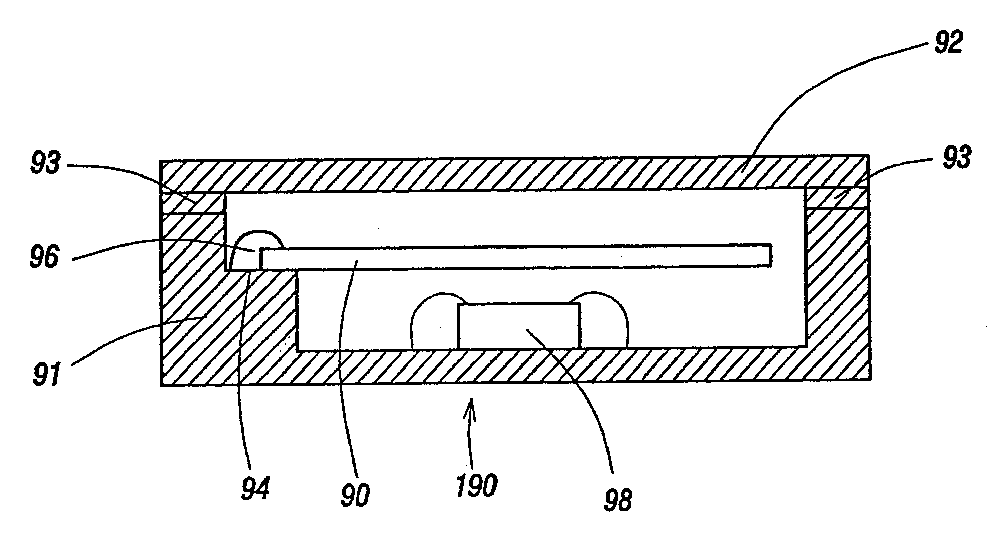
  • Method for manufacturing quartz crystal resonator
  • Method for manufacturing quartz crystal resonator
  • Method for manufacturing quartz crystal resonator

Examples


Embodiment Construction

[0028] Referring now to the drawings, the embodiments of the present invention will be described in more detail.

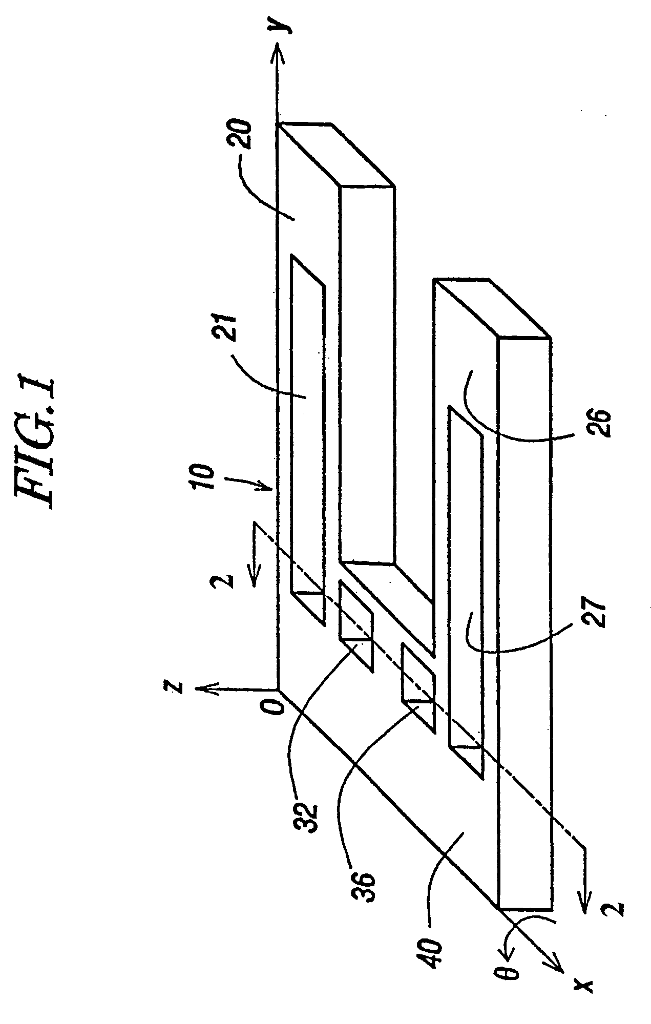
[0029]FIG. 1 shows a general view of a flexural mode, quartz crystal tuning fork resonator 10 embodying the present invention and its coordinate system o-xyz. A cut angle θ, which has a typical value of 0° to 10°, is rotated from a Z-plate perpendicular to the z axis about the x axis. The quartz crystal resonator 10 comprises two tuning fork tines 20 and 26 and a tuning fork base 40. The tines 20 and 26 have grooves 21 and 27 respectively, with the grooves 21 and 27 extending into the base 40. In addition, the base 40 has the additional grooves 32 and 36.

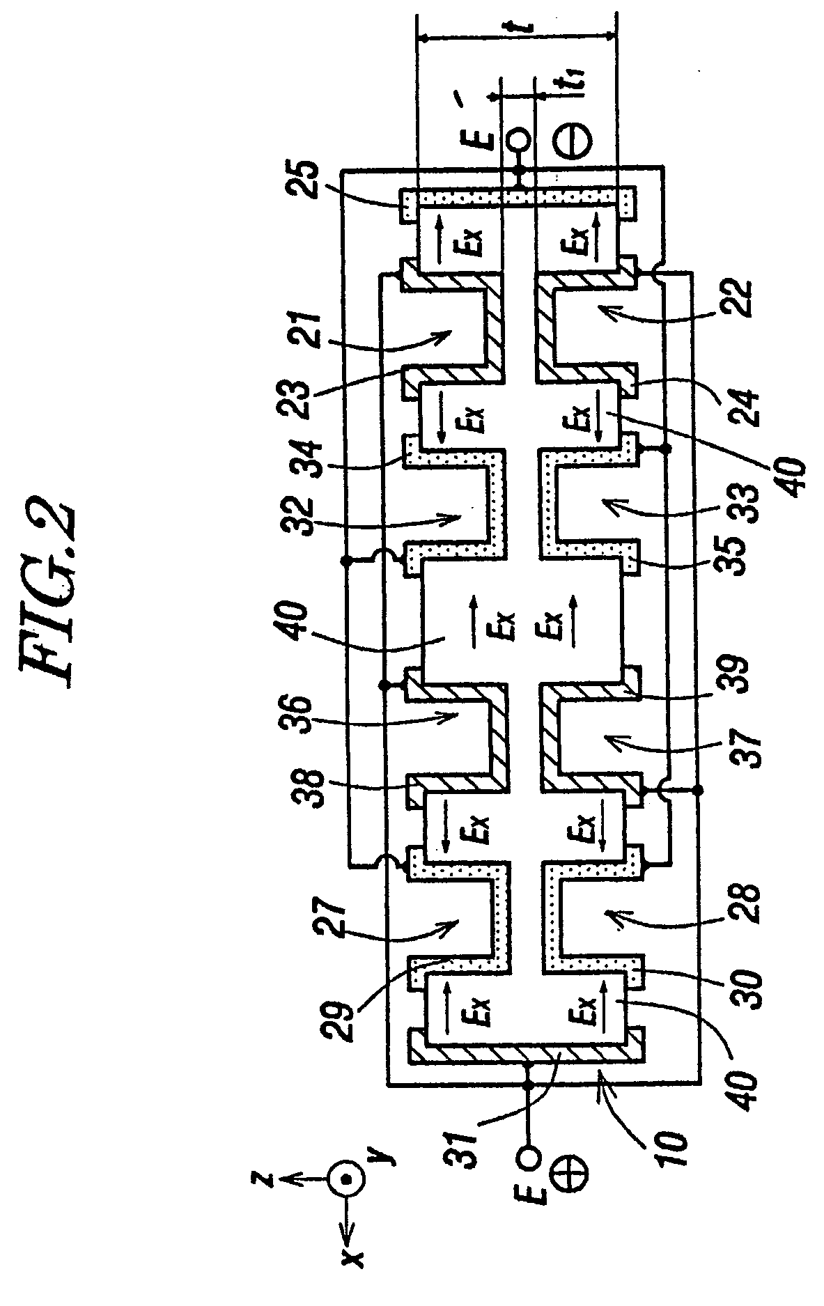
[0030]FIG. 2 shows a D-D′ cross-sectional view of the tuning fork base 40 for the quartz crystal resonator 10 of FIG. 1. In FIG. 2, the shape of the electrode construction within the base 40 for the quartz crystal resonator of FIG. 1 is described in detail. The section of the base 40 which couples to the tine 20 has the ...


PUM

PropertyMeasurementUnit
frequencyaaaaaaaaaa
frequencyaaaaaaaaaa
frequencyaaaaaaaaaa

Abstract

A quartz crystal tuning fork resonator is manufactured with a fundamental mode of vibration and a second overtone mode of vibration each comprised of a flexural mode of an inverse phase. A merit value M1 of the fundamental mode of vibration is greater than a merit value M2 of the second overtone mode of vibration thereof so that the second overtone mode of vibration is suppressed and a high frequency stability is obtained for the fundamental mode of vibration. The merit values M1 and M2 are defined by the ratios Q1 / r1 and Q2 / r2, respectively, where Q1 and Q2 represent a quality factor of the fundamental mode of vibration and the second overtone mode of vibration, respectively, and r1 and r2 represent a capacitance ratio of the fundamental mode of vibration and the second overtone mode of vibration, respectively, of the quartz crystal tuning fork resonator.

Description

FIELD OF THE INVENTION [0001] The present invention relates to a quartz crystal resonator, a quartz crystal unit and a quartz crystal oscillator, and their manufacturing methods. BACKGROUND OF THE INVENTION [0002] In general, a quartz crystal resonator is housed in a quartz crystal unit and a quartz crystal oscillator comprises the quartz crystal unit. For example, a quartz crystal oscillator with a quartz crystal unit comprising a contour mode resonator such as a quartz crystal tuning fork resonator, which is capable of vibrating in a flexural mode, is widely used as a time standard in consumer products, wearable time-keeping equipment and communication equipment (such as cellular phones, wristwatches and pagers). Recently, because of high frequency stability, miniaturization and the light weight nature of these products, the need for a smaller quartz crystal unit and a smaller quartz crystal oscillator with a smaller quartz crystal tuning fork resonator, capable of vibrating in a ...

Claims


Application Information

Patent Timeline
Patent Type & Authority Applications(United States)
IPC IPC(8): H01L41/09H01L41/18H01L41/22H01L41/23H01L41/253H01L41/313H03B5/36H03H3/02H03H3/04H03H9/02H03H9/05H03H9/10H03H9/19H03H9/21H03H9/215
CPCH03B5/36Y10T29/4913H03H9/1021H03H9/215H03H2003/0492H04R17/00Y10T29/49169Y10T29/42Y10T29/49002Y10T29/49004Y10T29/435Y10T29/49156Y10T29/49155Y10T29/49005Y10T29/43H03H9/0547
Inventor KAWASHIMA, HIROFUMI
Owner PIEDEK TECHN LAB
Learn More