
Nozzle for spraying sublimable solid particles entrained in gas for cleaning surface and method of cleaning surface using the same

a technology of sublimable solid particles and nozzles, which is applied in the direction of grinding machine components, chemistry apparatus and processes, manufacturing tools, etc., can solve the problems of air moisture condense on the surface of the nozzle, and the object to generate fros

Active Publication Date: 2005-12-01
K C TECH
View PDF25 Cites 35 Cited by
  • Summary
  • Abstract
  • Description
  • Claims
  • Application Information

AI Technical Summary

Benefits of technology

The present invention provides a nozzle for spraying sublimable solid particles for cleaning surfaces. The nozzle includes a cleaning agent block, a nozzle block, a carrier gas block, and a heater. The nozzle block has a plurality of inlet ports and a plurality of venturies for growing the cleaning agent snow. The carrier gas block has an inlet port and an outlet port. The nozzle can prevent frost formation on surfaces and at objects without the need for separate environmental control. The spray nozzle can be used in a multi-nozzle system. The method involves phase-changing the cleaning agent into a snow state containing sublimable solid particles, heating the carrier gas, and expanding the cleaning agent snow with the carrier gas before spraying it onto the surface. The invention provides a more efficient and effective method for cleaning surfaces with sublimable solid particles.

Problems solved by technology

However, since the cleaning method using the CO2 snow is performed at a very low temperature of not more than −60° C., moisture in the air may condense on the surfaces of the nozzle and the object to generate frost.
When frost is generated, contaminants in the air may attach to a surface of the substrate to seriously damage the semiconductor wafer or the LCD substrate, which requires a very fine cleaning process.

Method used


Image

  • Nozzle for spraying sublimable solid particles entrained in gas for cleaning surface and method of cleaning surface using the same
  • Nozzle for spraying sublimable solid particles entrained in gas for cleaning surface and method of cleaning surface using the same
  • Nozzle for spraying sublimable solid particles entrained in gas for cleaning surface and method of cleaning surface using the same

Examples


embodiment 1

Single Nozzle

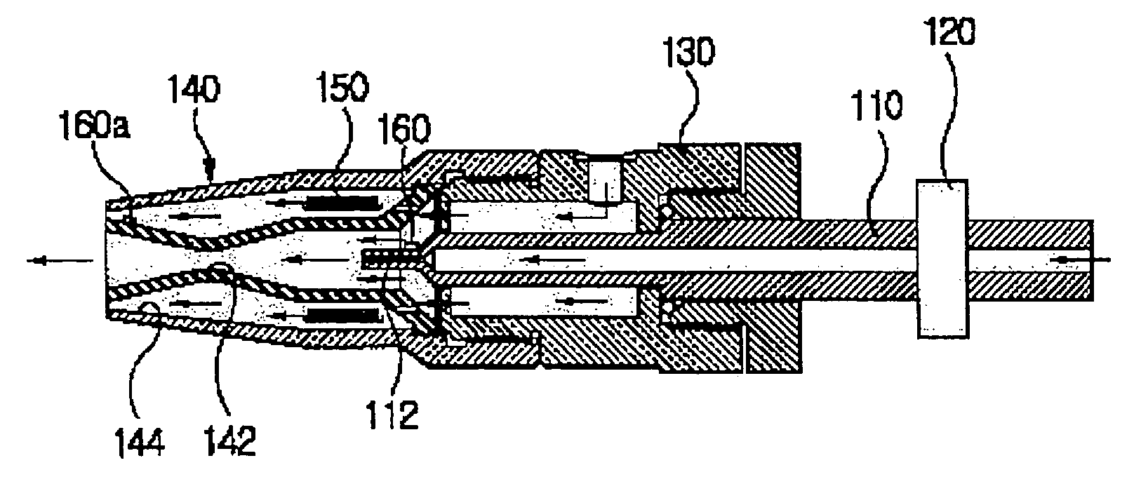
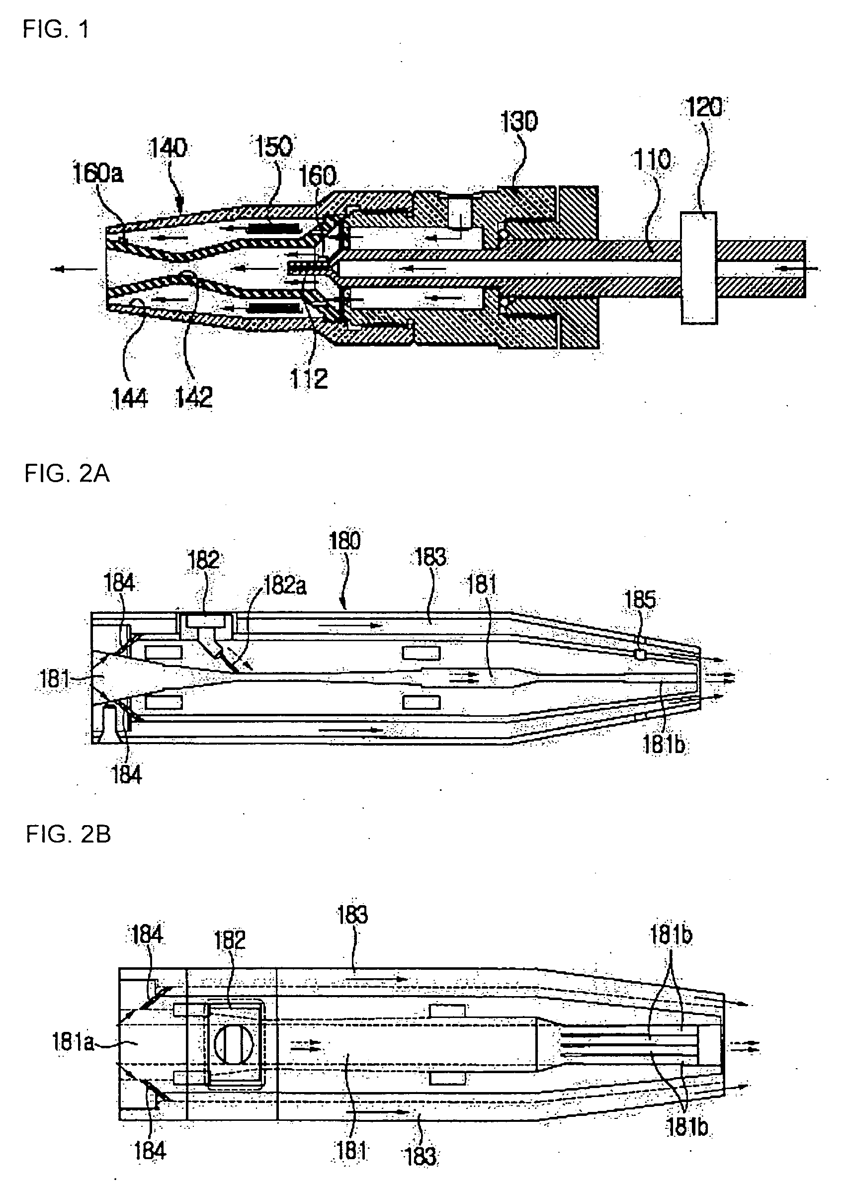
[0033]FIG. 1 illustrates a nozzle for spraying sublimable solid particles entrained in gas for cleaning a surface in accordance with a first embodiment of the present invention. The nozzle of FIG. 1 is a single nozzle having one outlet port for sublimable solid particles.

[0034] As shown in FIG. 1, the single nozzle in accordance with the present invention includes a cleaning agent block 110, a flow rate regulation valve 120, a carrier gas block 130, a nozzle block 140, and a heater 150. In this process, a cleaning agent is generally referred to as a sublimable material such as CO2, Ar, and so on, available for cleaning a surface of an object using the nozzle of the present invention.

[0035] The cleaning agent block 110 is a cylindrical pipe member that has an inlet port formed at a rear end and is in fluid communication with a cleaning agent supply source (not shown) such as a CO2 tank through a pipeline. An outlet port formed at a front end of the cleaning agent bloc...

embodiment 2

Multi Nozzle 1

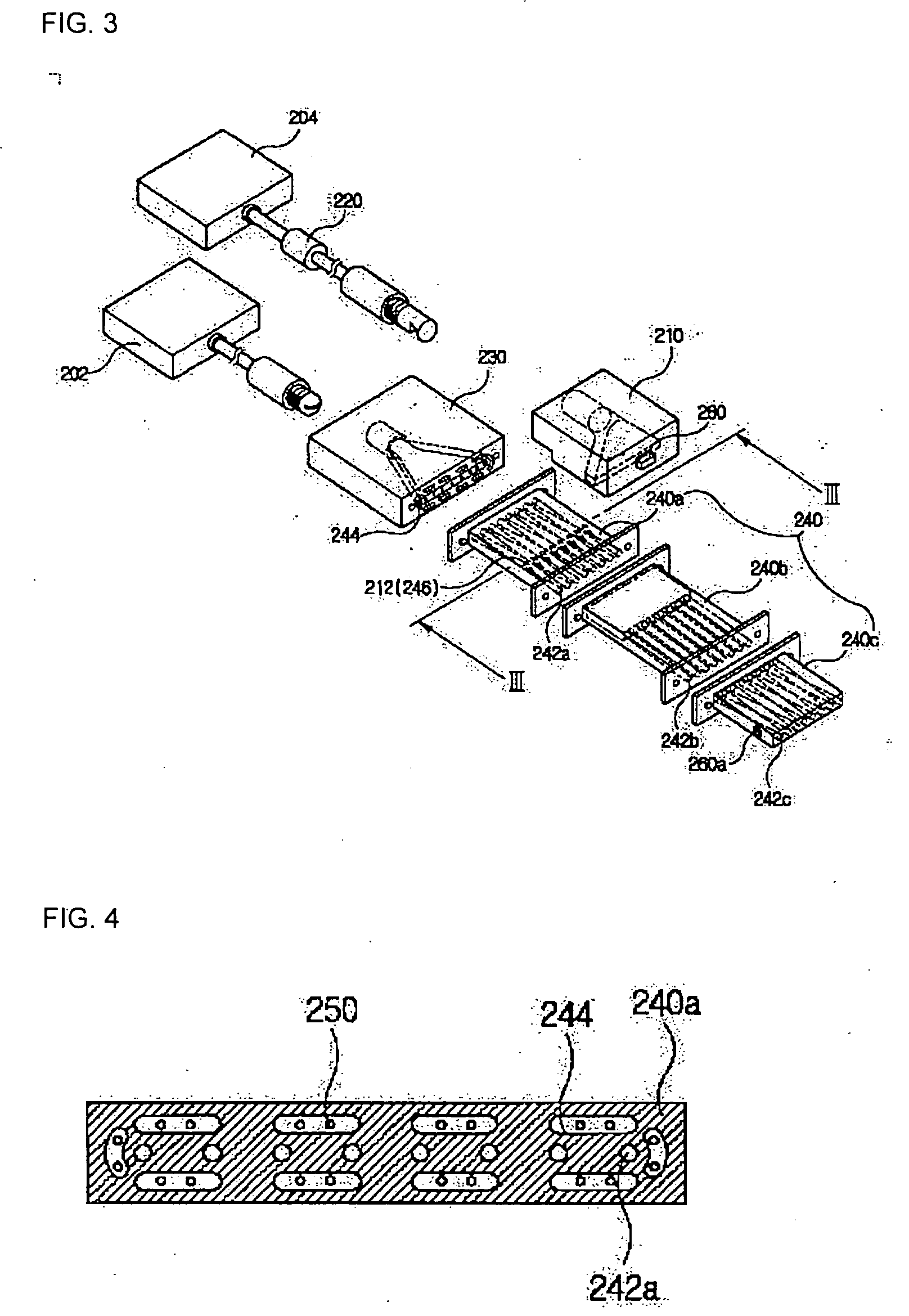
[0053]FIG. 3 is a perspective view of a spray nozzle according to a second embodiment of the present invention employing a multi nozzle, and FIG. 4 is a cross-sectional view taken along line III-III of FIG. 3. The embodiment of FIGS. 3 and 4 adds the technical spirit of the present invention to a multi nozzle described in W002 / 075799 A1, entitled “NOZZLE FOR INJECTING SUBLIMABLE SOLID PARTICLES ENTRAINED IN GAS FOR CLEANING SURFACE”, filed by the present applicant, the disclosure of which is incorporated herein in its entirety by reference.

[0054] As shown in FIGS. 3 and 4, the multi nozzle in accordance with the present invention includes a cleaning agent block 210, a carrier gas block 230, a nozzle block 240, and a heater 250. The nozzle block 240 may include a first venturi block 240a, and a second venturi block 240c, and may further include an intermediate block 240b interposed between the first and second venturi blocks 240a and 240c (the present embodiment inclu...

modified embodiment 2

Multi-Nozzle 2

[0064]FIG. 5 illustrates a modified example of the multi nozzle embodiment of FIGS. 3 and 4, and FIG. 6 is a cross-sectional view taken along line V-V of FIG. 5.

[0065] That is, the embodiment of FIGS. 5 and 6 is realized by moving a cleaning agent block 210′ to the inlet port of the first venturi block 240a from an upper part of the first venturi block 240a and installing a carrier gas block 230′ to surround a periphery of the cleaning agent block 210′, unlike the multi nozzle of FIGS. 3 and 4. The cleaning agent block 210′ and the carrier gas block 230′ of the embodiment of FIGS. 5 and 6 are engaged with each other, similar to the single nozzle.

[0066] The cleaning agent block 210′ has an outlet port located at an outlet side of the carrier gas block 230′ and includes a plurality of orifices 212′ parallelly spaced apart from each other. As a result, the cleaning agent ejected to an outlet space of the carrier gas block 230′ from the orifice 212′ of the cleaning agen...


PUM

PropertyMeasurementUnit
temperatureaaaaaaaaaa

Abstract

A nozzle for spraying sublimable solid particles and preventing frost from forming at surfaces of the nozzle. The nozzle includes: a cleaning agent block for phase-changing a cleaning agent into a snows containing sublimable solid particles; a nozzle block for growing the cleaning agent snow through adiabatic expansion and spraying the grown cleaning agent snow onto a surface of an object; a carrier gas block for supplying a carrier gas to the nozzle block to mix with the cleaning agent snow; and a heater for heating at least a portion of the carrier gas supplied from the carrier gas supply source. Fine dry ice particles and liquid CO2, passing through a solenoid valve from a CO2 reservoir tank and a pressure drop of a flow rate regulation valve, are introduced into the spray nozzle and then mixed with the carrier gas, such as N2 or purified air, and discharged.

Description

BACKGROUND OF THE INVENTION [0001] 1. Field of the Invention [0002] The present invention relates to a nozzle for spraying sublimable solid particles entrained in gas, such as CO2 snow or Ar snow, onto a surface of an object to be cleaned, and more particularly, to a nozzle for spraying sublimable solid particles capable of preventing frost from forming at surfaces of the nozzle and the object due to ultra-low temperature snow. [0003] 2. Description of the Related Art [0004] As is well known, fine contaminant particles can be removed from a surface of an object to be cleaned, such as a semiconductor wafer or an LCD (liquid crystal display) substrate, using CO2 mixed with solid particles and gases—so-called CO2 snow—without damaging the surface of the object. [0005] The CO2 snow passes through a venturi formed in a nozzle to generate solid particles which then grow and are sprayed onto the surface of the object to remove fine contaminant particles using impact energy of the solid par...

Claims


Application Information

Patent Timeline
Patent Type & Authority Applications(United States)
IPC IPC(8): B08B7/00B05B7/04B05B7/14B24B1/00B24C1/00B24C5/04H01L21/304
CPCB24C5/04B24C1/003H01L21/304
Inventor YOON, CHEOL-NAM
Owner K C TECH
Learn More