
Inkjet print head

a technology of inkjet printing and ink chamber, which is applied in the direction of printing and inking apparatus, etc., can solve the problems of lowering the performance of the inkjet printing head, inability to smoothly supply ink into the ink chamber, and contamination, etc., and achieves the effect of shortening the distance between the center and improving the printing speed

Inactive Publication Date: 2005-12-01
S PRINTING SOLUTION CO LTD
View PDF8 Cites 12 Cited by
  • Summary
  • Abstract
  • Description
  • Claims
  • Application Information

AI Technical Summary

Benefits of technology

[0017] Therefore, an aspect of the present general inventive concept provides an inkjet print head capable of improving a printing speed by shortening a distance between the center of a heater and an ink via.
[0018] It is also an aspect of the present general inventive concept to provide an inkjet print head capable of improving a printing speed by filtering various kinds of contaminants and simultaneously preventing grown bubbles from expanding toward an ink via to thereby shorten a refill time.
[0027] According to still another aspect of the present general inventive concept, the first protrusion may be configured to be perpendicular to a top surface of the heater in order to prevent bubbles generated by the heater from leaking toward the ink via.
[0029] The first protrusion may also have a width of two thirds or less compared to that of the restrictor channel at which the first protrusion may be located in order to prevent bubbles generated in the ink chamber from leaking toward the ink via.

Problems solved by technology

Meanwhile, contaminants or dust particles existing in the ink are responsible for lowering performance of the inkjet print head.
In other words, when the contaminants occlude an ink channel, the ink fails to be smoothly supplied into the ink chamber.
These contaminants may be introduced in the process of packaging the inkjet print head as well as the ink cartridge.
In particular, fine contaminants may still exist in the ink even after the ink passes through a filter of the cartridge.
In addition, the inkjet print head 200 shown in FIG. 1B has a problem in that, because the restrictors 260 are provided to the nozzles respectively, at least one of inlets of the nozzles may be blocked by the contaminants which may be generated during the process of packaging the head and cartridge, and thus the ink can not be ejected through the blocked nozzle.

Method used


Image

  • Inkjet print head
  • Inkjet print head
  • Inkjet print head

Examples


Embodiment Construction

[0048] Reference will now be made in detail to the embodiments of the present general inventive concept, examples of which are illustrated in the accompanying drawings, wherein like reference numerals refer to the like elements throughout. The embodiments are described below in order to explain the present general inventive concept by referring to the figures.

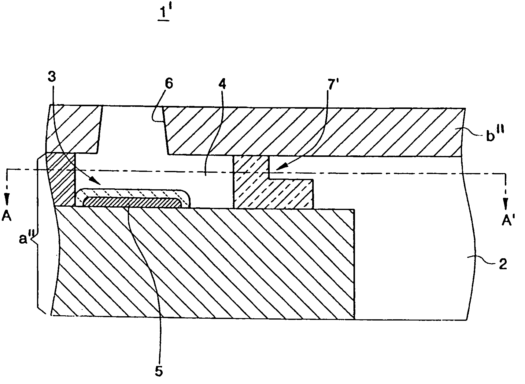
[0049]FIG. 2A is a vertical cross-sectional view illustrating, on a magnified scale, a part of an inkjet print head 1 according to an embodiment of the present general inventive concept. FIG. 2B is a plan view of the inkjet print 1 in which a nozzle layer b′ is separated therefrom.

[0050] Referring to FIGS. 2A and 2B, the inkjet print head 1 may comprise a chamber layer a′ formed of a plurality of thin layers on a substrate. The chamber layer a′ may be provided with an ink via 2 and an ink chamber 3, which may be connected to each other by an ink channel 4. The ink chamber 3 may be provided with a heater 5 or a resistance heat...


PUM


Abstract

An inkjet print head including a chamber layer provided with an ink via, at least one ink chamber having a heater, and at least one ink channel connecting the ink via and the ink chamber; and a nozzle layer provided with at least one nozzle at a position corresponding to the ink chamber. The ink channel is provided with a multi-functional structure. The multi-functional structure performs functions of a filter and a restrictor.

Description

CROSS-REFERENCE TO RELATED APPLICATIONS [0001] This application claims the benefit of Korean Patent Application No. 2004-37545, filed on May 25, 2004, the disclosure of which is hereby incorporated herein by reference and in its entirety. BACKGROUND OF THE INVENTION [0002] 1. Field of the Invention [0003] The present general inventive concept relates to an inkjet print head, and more particularly, to an inkjet print head performing a mechanism to eject droplets of ink based on a thermal driving type. [0004] 2. Description of the Related Art [0005] An inkjet print head is a device for ejecting droplets of ink supplied from an ink cartridge toward a desired position on a printing medium and forming an image such as a character or a picture. The inkjet print head is generally divided into two types, a thermal driving type and a piezoelectric driving type, according to a mechanism ejecting the ink droplets. The thermal driving type inkjet print head makes use of a heater and generates b...

Claims


Application Information

Patent Timeline
IPC IPC(8): B41J2/14B41J2/05B41J2/175B41J2/19
CPCB41J2/1404B41J2202/07B41J2002/14403B41J2/17563
Inventor KIM, KWANG-RYUL
Owner S PRINTING SOLUTION CO LTD
Learn More